
Promoting the electrochemical properties of yolk-shell-structured CeO2 composites for lithium-ion batteries
 0
0Abstract
Lithium-ion batteries offer significant convenience to modern portable technology and our daily lives due to their high energy density and cycling capabilities. Cerium oxides are attracting significant attention as Li-ion battery anode materials due to their nontoxicity and fast redox kinetics. However, these anodes face critical issues, such as poor electronic conductivity and serve volume expansion upon Li-ion intercalation. Herein, yolk-shell-structured CeO2 encapsulated in mesoporous carbon nanospheres (CeO2@void@C) is proposed with an adjustable void between the CeO2 core and the outer carbon layer. A significantly enhanced capacity and rate performance are obtained for the target CeO2@void@C when compared with the untreated CeO2 anode. The reversible capacity of CeO2@void@C is double that of the untreated CeO2 anode. Additionally, the yolk-shell-structured CeO2 shows a slow capacity decay and maintains a capacity of 210 mAh·g-1 at a current density of 1000 mA·g-1 with a ~100% Coulombic efficiency even after 1000 cycles. This improvement originates from the conductivity of the coating carbon layer and the void that constrains the volume change upon electrochemical lithiation/delithiation.
Keywords
INTRODUCTION
With the development of society, carbon neutralization has been augmented immensely due to the consumption of fossil fuels and climate change. There are significant demands for the development of renewable energy and storage technologies. Among the various energy storage systems, lithium-ion batteries (LIBs) are considered as promising energy storage devices due to their high energy density and specific power and long cycle life[1-4]. Rapid charging/discharging technology is currently being increasingly investigated worldwide, which makes the development of new LIBs that provide stable cyclic stability and fast rate capability increasingly more urgent[5,6]. However, it is difficult to satisfy these requirements since traditional graphite is limited by a theoretical specific capacity of only 372 mAh·g-1. Simultaneously, the capacity of batteries with graphite anodes rapidly decreases to ~66% after 100 cycles[7]. The demands of high electrochemical performance have engendered the search for alternative anode materials, including carbonaceous materials[8-11], carbon-silicon composites[12,13] and transition metal compounds[14-19]. Rare earth anode materials have also been widely investigated because of their low redox voltage, high cycling rates and other promising properties[20-22].
Cerium oxide (CeO2) has been widely explored in the fields of supercapacitors, LIBs, catalytic supports in fuel cells and gas sensors[23-25] due to its oxygen deficiency and the fast mutation between Ce(III) and Ce(IV)[26-28]. Bare CeO2 films[29], core-shell nanospheres[27], hollow spheres[30] and CeO2/carbon composites[31] have all been investigated as LIB anodes. The basic working mechanism of cerium oxide in a LIB charge/discharge procedure can be described as[27]:
2CeO2 + 2Li+ + 2e- ⇔ Ce2O3 + Li2O
However, the main residual issues of cerium oxide as an anode material are low electronic conductivity and a crystal structure crushing (shatter effect) during cycling. To solve these issues, researchers have dedicated considerable effort to constructing composites with materials such as carbon-coated TiO2[32,33], SnO2[34-36] and Fe3O4[37,38] to markedly enhance the electrochemical properties of cerium oxide. Structures compounded with carbon can effectively confine the matrix to alleviate volume changes and obstruct the aggregation of active particles. For oxide and sulfide anodes, due to the prominent volume expansion during Li+ intercalation/deintercalation, the use of core-shell structures may result in stress fractures and exfoliation[27]. Inspired by previous studies, an attractive strategy to fabricate yolk-shell structures with tunable void spaces was proposed for CeO2 with the aid of an outer carbon layer to avoid damage to the architecture[39].
In this contribution, we report the design and synthesis of yolk-shell-structured CeO2@void@C using a self-template strategy method. First, uniform CeO2 nanospheres are synthesized from a solvothermal method. A layer of SiO2 is then coated on the surface of CeO2 to form CeO2@SiO2, which is further solved in a resorcinol formaldehyde (RF) solution to obtain core-shell-structured CeO2@SiO2@RF. By annealing and etching, the target CeO2@void@C is obtained and fully characterized by structural determination and electrochemical investigations. The electrochemical performance of CeO2@void@C is demonstrated according to its well-designed nanoarchitecture. The electrochemical reaction mechanisms are probed by X-ray diffraction (XRD) and nuclear magnetic resonance (NMR) spectroscopy.
MATERIALS AND METHODS
Materials
The raw materials of cerium carbonate hexahydrate [Ce2(CO3)3·6H2O], ethylene glycol (CH2OH)2, ethanol (ETOH), glacial acetic acid (CH3COOH), sodium citrate (C6H5Na3O7), resorcinol [C6H4(OH)2], tetraethylorthosilicate, ammonia solution, formaldehyde and sodium hydroxide solution were purchased from MACKLIN and used without further purification. LiPF6 (1 M), N-methyl-2-pyrrolidine, polyvinylidene fluoride and a Celgard 2400 separator were used for the electrochemical experiments.
Sample preparation and characterization
Synthesis of yolk-shell-structured CeO2@void@C nanospheres
Initially, uniform CeO2 nanospheres were synthesized by a hydrothermal method and adopted as the initial materials. Typically, 1 g of Ce2(CO3)3·6H2O was dissolved in 1 mL of deionized water, with 1 mL of glacial acetic acid, 0.1 g of sodium citrate and 30 mL glycol then added. The mixture was stirred for 30 min and then transferred to a Teflon-lined hydrothermal autoclave, which was heated at 180 °C for 4 h. The product was washed with ethanol and deionized water three times and placed in a blast drying oven at 60 °C for 12 h to obtain the homogenous CeO2 nanospheres.
The yolk-shell-structured CeO2@void@C was prepared using the following steps. First, 0.1 g of CeO2 nanospheres were dispersed in a 140 mL ethanol-water (1:6) solvent mixture via ultrasonic treatment for
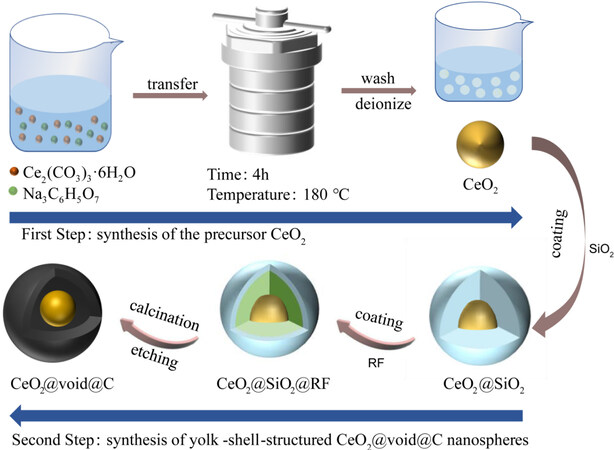
Figure 1. Schematic of preparation process for yolk-shell-structured CeO2@void@C nanospheres.
Structure and morphological characterization
Crystal structures were determined using a PANalytical Empyrean X-ray diffractometer. The morphologies were characterized by scanning electron microscopy (SEM) with a JSM-7900F field emission scanning electron microscope. Thermogravimetric analysis (TGA) was performed on a Netzsch STA449 F5/F3 Jupiter thermal analyzer. The Raman spectra were determined using an inVia™ confocal Raman microscope. The specific surface area and aperture of the samples were measured by an ASAP2460 physical adsorption analyzer. The chemical states of the samples were studied with X-ray photoelectron spectroscopy (XPS) using a Thermo ESCALAB 250xi. The microscopic crystal structures were characterized using transmission electron microscopy (TEM) with a JEM-F200 field emission transmission electron microscope. Solid-state
Electrochemical characterization
Lithium foil was employed as the counter electrode for the evaluation of the electrochemical performance. The active materials (yolk-shell-structured CeO2@void@C or bare CeO2), conductivity agent (Super P) and polyvinylidene fluoride in a weight ratio of 60:30:10 were mixed with the N-methyl-2-pyrrolidine solvent to generate a homogenous slurry. It was then painted onto Cu foil and dried at 80 °C overnight under a vacuum. LiPF6 (1 M) was solved in diethyl carbonate/dimethyl carbonate/ethylene carbonate (1:1:1 vol.%) with the addition of 10 wt.% fluorinated ethylene carbonate to serve as the electrolyte. Celgard 2400 was used as the separator. The batteries were assembled in CR2032 coin cells. The electrochemical performance was studied through a Lanthe CT2001A/B testing system. Electrochemical impedance spectroscopy (EIS) was carried out using an SP-150 workstation (BioLogic, France).
RESULTS AND DISCUSSION
To make the synthesis procedure clearer, the complete routine is presented in Figure 1. First, CeO2 nanoparticles were obtained using a solvothermal method, in which the homogenous mixture of
XRD was performed to determine the crystal structures of the as-synthesized materials. Cubic CeO2 nanospheres were successfully synthesized according to the XRD patterns [Figure 2A], in which the peaks at 28.6°, 33.1°, 47.5° and 56.3° correspond to the (111), (200), (220) and (311) crystal faces, respectively. No position shifts were observed for pure CeO2 or CeO2@void@C, indicating that the coating treatment does not influence the lattice parameters of the CeO2 core. However, all the peaks became sharper for the yolk-shell-structured CeO2@void@C, which should be attributed to the annealing process at 600 °C, resulting in a better crystalline phase. Additionally, there is no diffraction peak detected for carbon, revealing that the coating layer is amorphous. The Raman spectra of CeO2 and CeO2@void@C were also characterized [Figure 2B]. The peak at 460 cm-1 for the characterization of the F2g vibration was detected for both CeO2 and CeO2@void@C[27]. For the yolk-shell-structured CeO2@void@C, two extra intensive broad peaks at 1338 and 1588 cm-1 were observed, which could be assigned to the D band (disorder induction) and G band (graphite), respectively. The intensity ratio of the D and G bands (ID/IG) was referenced to evaluate the graphitization degree[5]. The ID/IG ratio was calculated as ~0.844 for CeO2@void@C, which reveals good graphitization and electronic conductivity, resulting in faster cycling rate performance of CeO2@void@C when compared with the untreated CeO2.
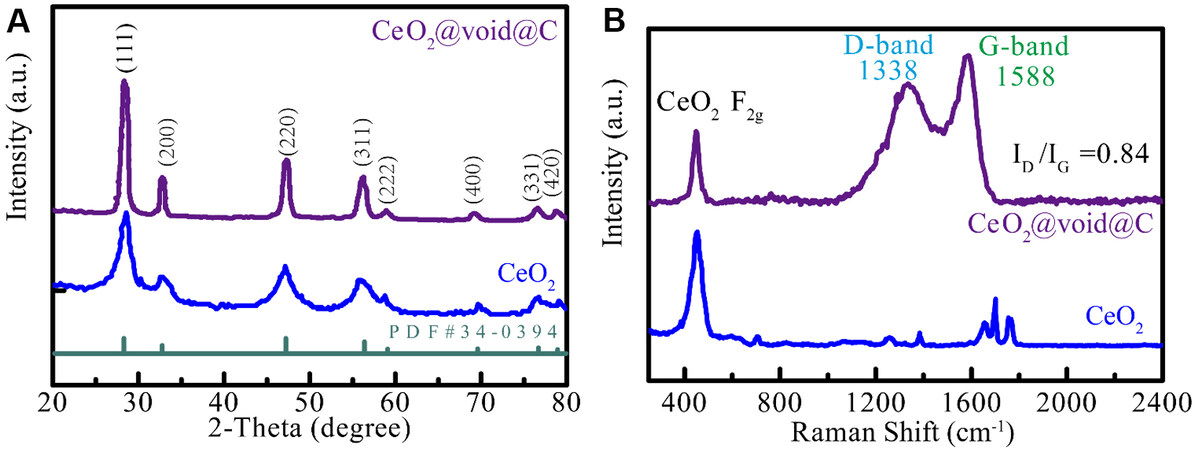
Figure 2. (A) X-ray diffraction patterns of untreated CeO2 and CeO2@void@C. (B) Raman spectra of CeO2 and CeO2@void@C.
The morphologies of CeO2 and CeO2@void@C are displayed in Figure 3 and are homogeneously distributed in size. As shown in Figure 3A and C, the particle diameters of both CeO2 and CeO2@void@C are ~100 and ~220 nm, respectively. The tapped density of the anode has a certain impact on the performance and specific capacity and depends on the intrinsic density and particle size distribution. A higher intrinsic density and narrower particle size distribution result in a higher tapped density. Although there is a certain space between the core and shell, the high density core and homogeneous particle size ensure good tapped density. The good tapped capacity could be further improved by optimizing the void volume between the CeO2 core and the carbon shell. The etching and annealing process does not change the size of the carbon coating layer when compared to Figure 3B and C. The high-resolution TEM images of pure CeO2 are shown in Figure 3E.
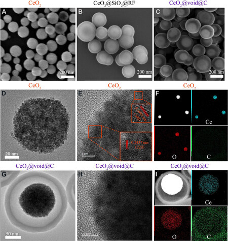
Figure 3. Scanning electron microscopy images of (A) CeO2, (B) CeO2@SiO2@RF and (C) CeO2@void@C. High-resolution transmission electron microscopy images of (D, E) CeO2 and (G, H) CeO2@void@C. EDS elemental maps of (F) CeO2 and (I) CeO2@void@C.
The lattice fringe spacing of CeO2 is in good agreement with the XRD patterns [Figure 2]. The energy dispersive X-ray spectrum elemental mapping images indicate that Ce and O are homogenous for CeO2 [Figure 3F]. Obviously, there is no signal for carbon in the CeO2 sample. With regards to the CeO2@void@C sample, the carbon coating layer is determined as being ~20 nm thick, as shown in Figure 3G. An obvious void space is found between the CeO2 core and the carbon layer [Figure 3C and G]. Due to the shielding of the carbon layer, the lattice fringe is not clear for the coated CeO2@void@C [Figure 3H]. The elemental mappings show that both Ce and O are localized within the CeO2 core [Figure 3I], while carbon is distributed at the outer layer. To check the stability of the structure, cycled samples were also measured. CeO2@void@C maintains good morphology after cycling [Supplementary Figure 1]. However, the CeO2 nanoparticles without the carbon shell agglomerated badly after 100 cycling scans [Supplementary Figure 2].
The surface area and pore size distribution were determined by nitrogen adsorption-desorption isotherms. The specific surface of the untreated CeO2 [Figure 4A] is only 26 m2·g-1 and was obtained by the Brunauer-Emmett-Teller method. In comparison, the specific surface area increases profoundly to 166 m2·g-1
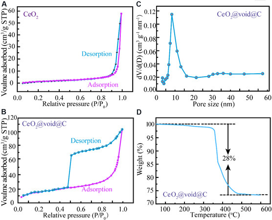
Figure 4. N2 adsorption-desorption isotherms of as-prepared CeO2 (A) and CeO2@void@C (B). (C) Pore size distribution of
XPS was carried out to investigate the surficial elements and valence states of CeO2@void@C. All signals of Ce, O and C appear in the full spectrum [Figure 5A]. For the CeO2@void@C [Figure 5B], the XPS spectrum of Ce 3d included five peaks of Ce 3d3/2 and three peaks of Ce 3d5/2[41]. Based on the signal integration of Ce 3d5/2, the peaks of Ce4+ are located at 879.8 and 886.5 eV, while one peak of Ce3+ is located at 883.0 eV. The corresponding areas were integrated and the ratio of Ce3+ and Ce4+ is 31:69, which could be approximated as the atomic fractions in redox states. The Ce 4d peak in the full survey also belongs to
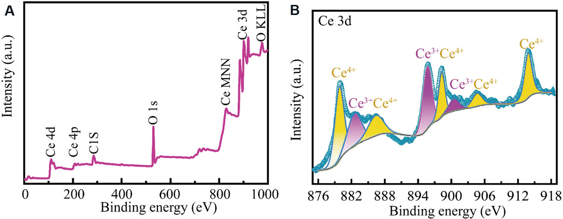
Figure 5. (A) Full X-ray photoelectron spectroscopy (XPS) spectrum of CeO2@void@C. (B) High-resolution XPS spectrum and simulation of Ce 3d for CeO2@void@C.
The electrochemical properties were fully investigated for the in-depth study of the potential application and mechanism of CeO2@void@C. Figure 6A shows the cyclic voltammetry (CV) analysis of CeO2@void@C at a scan rate of 0.1 mV·s-1 in the voltage range of 0.01 to 3.00 V. In the first cathodic polarization process, two broad cathodic peaks were observed. The first cycle is partially irreversible because of side reactions, such as electrolyte decomposition and the formation of a solid electrolyte interface (SEI) film. The cathodic peak (1.24 V) was observed only in the first cycle, which can be attributed to the initial insertion of Li ions and the breakdown of electrolytes. After the first cycle, the following cathodic peak located between 0.8 and 0.1 V may be ascribed to the reductive transformation of CeO2 to Ce2O3 and Li2O according to the conversion reaction. The CV curves quickly become stable and the discharge-charge curves almost overlap with each other, indicating that the electrochemical reactions are highly reversible for CeO2@void@C.
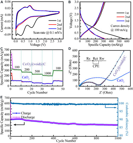
Figure 6. (A) Cyclic voltammetry of CeO2@void@C at a scan rate of 0.1 mV·s-1 at room temperature. (B) Cycling performance of
Figure 6B shows the first three electrochemical cycles of a Li//CeO2@void@C battery at a current density of 100 mA·g-1. The initial discharge and charge capacities were characterized as 615 and 321.13 mAh·g-1, respectively, with a Coulombic efficiency of 51.38%. The initial irreversible capacity loss is mainly due to the electrolyte decomposition, the formation of an SEI film and the irreversible formation of Li2O. During the second and third circles, the discharge and charge contours are almost identical, reflecting the excellent structural stability of the electrode. Figure 6C compares the rate performances of the untreated CeO2 and the CeO2@void@C electrodes. With increasing current density from 100 to 200, 500 and 1000 mA·g-1, the Li//CeO2@void@C battery delivered reversible discharge capacities of 313, 265, 227 and 196 mAh·g-1, respectively. For the Li//CeO2 battery, the capacities are determined only as 104.8, 84.1, 61.2 and 50 mAh·g-1 under the corresponding current densities. The capacity of the Li//CeO2@void@C battery was maintained at ~300 mAh·g-1 and 100 mAh·g-1 was recovered for the Li//CeO2 battery when the current density was restored to 100 mAh·g-1. Along with all different applied currents, the capacities of CeO2@void@C are almost three times those obtained for the untreated CeO2.
EIS of CeO2@void@C and untreated CeO2 was performed to determine their resistance and diffusion behavior [Figure 6D]. The impedance data were fitted as an equivalent electrical circuit, which is composed of the solution resistance (Rs), the charge transfer resistance (Rct), the constant phase element and the Warburg impedance (Rw)[42]. The analyzed impedance results are listed in Table 1. The values of Rct for the CeO2@void@C anode and the untreated CeO2 anode were calculated to be 232.5 and 464 Ohm, respectively. Obviously, faster kinetics in the electrochemical reactions exist for the CeO2@void@C anode compared to the untreated CeO2. The total resistance of CeO2 is larger than that of the CeO2@void@C as an electrode. The long-term cycling performance was also tested [Figure 6E] and the capacity gradually decreases from ~300 to ~200 mAh·g-1 at a current density of 100 mAh·g-1 after 1000 cycles. The initial 50 cycles are shown in Supplementary Figure 3 for better comparison. Surprisingly, CeO2@void@C shows an excellent Coulombic efficiency of 100% due to the structural stability endowed by the buffer space.
Impedance parameters calculated from EIS
| Material | Rs (Ohm) | Rct (Ohm) |
| Bare CeO2 | 49.7 | 464 |
| CeO2@void@C | 2.9 | 232.5 |
To understand the electrochemical mechanism of the CeO2@void@C anode, CV was carried out under different rates, as shown in Figure 7A. The storage mechanism is manipulated by two types of process, namely, diffusion-controlled behavior and pseudocapacitive storage, which can be estimated by the ratio of the square root of current and the scan rate as the factor of b values[43,44]. The process is completely controlled by ion diffusion when b is 0.5, while the capacitance effect dominates when b is 1. As shown in Figure 7B, b values of 0.93 and 0.84 are determined for peaks 1 and 2, respectively, revealing a pseudocapacitive behavior for CeO2@void@C. A pseudocapacitive contribution of 77.3% at a 0.8 mV·s-1 scanning rate is determined for the CeO2@void@C anode, as calculated in Figure 7C. By varying the scan rate [Figure 7D], the pseudocapacitive contributions are 54.3%, 60.1%, 68.6%, 70.5%, 73.4%, 75.9% and 77.3% under scanning rates of 0.1, 0.2, 0.3, 0.4, 0.5, 0.6, 0.7 and 0.8 mV·s-1, respectively. Therefore, the pseudocapacitive process shows a significant role in the total capacity and its contribution grows with increasing scanning rate.
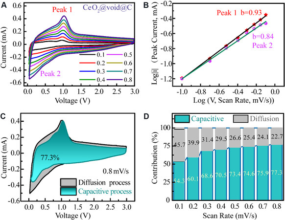
Figure 7. (A) Cyclic voltammetry curves of CeO2@void@C electrode under different scan rates. (B) Fitting of the square root of the peak current and the scan rate (v1/2). (C) Capacitive contribution of CeO2@void@C to the total storage. (D) Contribution ratios of the capacitive and diffusion-controlled process under various scan rates.
Ex-situ XRD at the first cycle was carried out to investigate the component and crystal structure variation of CeO2@void@C. Certain cycling states of the batteries were selected, as marked to the right of Figure 8. The XRD pattern of the pristine anode shows the pure phase of CeO2. Upon discharge, the diffraction peak slightly shifted to a lower value of 2θ, which is consistent with the peak position trend of Ce2O3. Meanwhile, lithium ions are embedded in the lattice, making the lattice parameters larger. Thus, the partial formation of the Ce2O3 phase structure and cell volume expansion are confirmed during lithiation. In the subsequent charge process, the peaks inversely move back to larger 2θ values, which could be due to the extraction of Li ions, causing oxidation of Ce3+ to Ce4+ and cell shrinking. The peak positions of the fully charged sample are still slightly lower than those of the pristine material, which is attributed to the irreversible reaction and residual lithium ions. No new phase was detected in the whole charge/discharge process. Therefore, the electrochemical cycling of the CeO2@void@C electrode could be considered as an intercalation/extraction reaction process.
NMR is very sensitive to the Li-ion local environment of battery materials[45,46]. The solid-state 7Li NMR spectra of LixCeO2@void@C electrodes at different cycling states are shown in Figure 9. As shown in Figure 9A, all the electrodes show wide spinning sidebands ranging from -600 to 600 ppm because of the anisotropy of Li, together with the possible hyperfine interaction between the unpaired electrons of Ce3+/4+. The electrode discharged to 1.1 V (bottom spectrum in Figure 9A) presents a sharp symmetric peak at
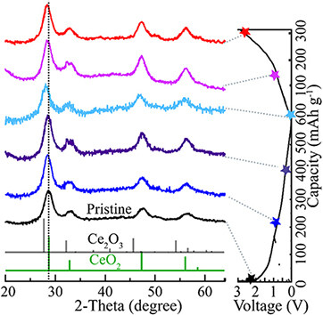
Figure 8. Ex-situ XRD of CeO2@void@C at various cycling states. The corresponding electrochemical curve is displayed to the right. For better comparison, the indexes of both CeO2 and Ce2O3 are also plotted for reference.
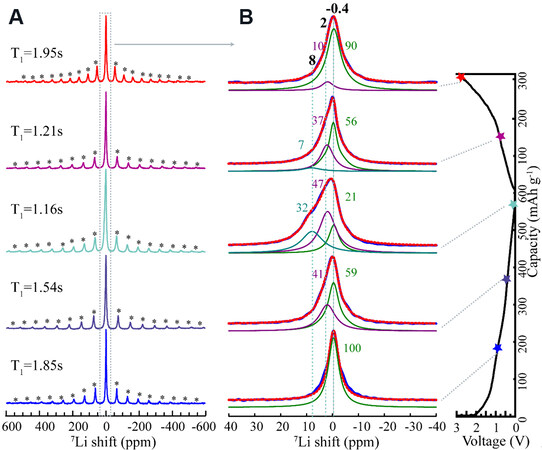
Figure 9. Solid-state 7Li NMR spectra of cycled CeO2@void@C electrodes at different states. (A) Full spectra with the spinning sidebands marked with asterisks. The corresponding longitudinal relaxation time T1 is noted to each spectrum. (B) The simulation region of the isotropic signal is marked by the rectangular dotted frame, as shown in (A). Blue signals are obtained from experiment and red-dashed curves are the sum of deconvolution. The chemical shifts and occupancies are marked for each simulated peak.
For a clearer discussion, the spectra are simulated and the deconvoluted spectra of the isotropic resonances are presented in Figure 9B. For the electrode discharged to 1.1 V, only one peak at -0.4 ppm is simulated, which is possibly originated from the SEI components, such as LiF and Li2CO3[47]. When the anode is further discharged to 0.4 V, an additional peak at 2 ppm with 41% occupancy appears in addition to the first peak at -0.4 ppm, which accounts for 59%. The signal at 2 ppm is mainly assigned to the product Li2O. Deeper lithiation to 0.01 V produces an extra signal at even downfield to 8 ppm, with an occupancy of 32%. The change of Fermi contact along the Ce-O-Li bond is the main reason for the spectral shifts, as the electron cloud varies due to the reduction of Ce4+ to Ce3+ upon discharge, or different sites/vacancies are occupied by the intercalated Li+. Upon subsequent charge, a reverse trend is observed. When the electrode is charged to 1 V, the signals at 8 and 2 ppm decrease to 7% and 37% from 32% and 47%, respectively. When the battery is further charged to 3 V, the signal at 8 ppm disappeared completely and 10% is still residual for the signal at 2 ppm caused by the irreversible reaction. Furthermore, the relaxation time T1 decreases upon discharge due to the reduction of Ce4+ to Ce3+, with the latter displaying stronger paramagnetization. This is regained upon the following charge because of reverse evolution. The NMR results are in good agreement with the above-mentioned XRD study.
CONCLUSIONS
In summary, yolk-shell-nanostructured CeO2@void@C was designed and its electrochemical properties were fully investigated as an anode for LIBs. Both good electronic conductivity and enhanced capacity were achieved according to the hollow carbon shell composite structure of CeO2@void@C. Furthermore, the excellent cycling stability was further confirmed by the fast charge transfer and long-term cycling test. The structure-property correlation proposes a promising strategy for fabricating nanosized CeO2 cores and carbon shells with adjustable voids, which show enhanced lithium storage properties. XRD and NMR analysis reveals that the intercalation process dominates the lithiation/delithiation reaction for the
DECLARATIONS
AcknowledgmentsThe authors thank Dr. Yonggang Wang and Dr. Kuo Li for helpful discussion. The platform of HPSTAR is acknowledged.
Authors’ contributionsPerformed materials synthesis and electrochemical experiments, together with data collection and analysis: Shi Y, Hui K
Made substantial contributions to conception and design of the materials and data analysis and interpretation: Fu J, Tang M
Performed TEM, SEM data acquisition and analysis: Chen Y, Gao C, Gao X
NMR measurements and analysis: Liu J, Chang S, Xu L, Wei Q, Tang M
All authors contribute to the manuscript and are involved in discussion.
Availability of data and materialsData can be deposited into data repositories or published as supplementary information in the journal.
Financial support and sponsorshipThis work was supported by the National Natural Science Foundation of China (Grants 21974007, U1930401 and U1530402) and the Natural Science Foundation of Zhejiang Province (Grant No. LQ21E020006).
Conflicts of interestAll authors declared that there are no conflicts of interest.
Ethical approval and consent to participateNot applicable.
Consent for publicationNot applicable.
Copyright© The Author(s) 2021.
Supplementry Materials
REFERENCES
1. Tarascon J, Armand M. . Issues and challenges facing rechargeable lithium batteries. Materials for Sustainable Energy. Co-Published with Macmillan Publishers Ltd, UK; 2010. p. 171-9.
2. Kang K, Meng YS, Bréger J, Grey CP, Ceder G. Electrodes with high power and high capacity for rechargeable lithium batteries. Science 2006;311:977-80.
3. Xu K. Nonaqueous liquid electrolytes for lithium-based rechargeable batteries. Chem Rev 2004;104:4303-417.
5. Xia H, Li K, Guo Y, Guo J, Xu Q, Zhang J. CoS2 nanodots trapped within graphitic structured N-doped carbon spheres with efficient performances for lithium storage. J Mater Chem A 2018;6:7148-54.
6. Wang S, Guan BY, Yu L, Lou XWD. Rational design of three-layered TiO2 @Carbon@MoS2 hierarchical nanotubes for enhanced lithium storage. Adv Mater 2017;29:1702724.
7. Lee SM, Kim J, Moon J, et al. A cooperative biphasic MoOx-MoPx promoter enables a fast-charging lithium-ion battery. Nat Commun 2021;12:39.
8. Pei F, An T, Zang J, et al. From hollow carbon spheres to N-doped hollow porous carbon bowls: rational design of hollow carbon host for Li-S batteries. Adv Energy Mater 2016;6:1502539.
9. Wu J, Rui X, Long G, Chen W, Yan Q, Zhang Q. Pushing up lithium storage through nanostructured polyazaacene analogues as anode. Angew Chem Int Ed Engl 2015;54:7354-8.
10. Zhu Y, Yang M, Huang Q, et al. V2O5 textile cathodes with high capacity and stability for flexible lithium-ion batteries. Adv Mater 2020;32:e1906205.
11. Wang J, Cui Y, Wang D. Hollow multishelled structures revive high energy density batteries. Nanoscale Horiz 2020;5:1287-92.
12. Xiao Q, Fan Y, Wang X, Susantyoko RA, Zhang Q. A multilayer Si/CNT coaxial nanofiber LIB anode with a high areal capacity. Energy Environ Sci 2014;7:655-61.
13. Polat B, Levent Eryılmaz O, Keleş O. Si based anodes via magnetron sputtering for LIB. ECS Electrochemistry Letters 2014;3:A45-9.
14. Varghese B, Reddy MV, Yanwu Z, et al. Fabrication of NiO nanowall electrodes for high performance lithium ion battery. Chem Mater 2008;20:3360-7.
15. Yu M, Wang A, Wang Y, Li C, Shi G. An alumina stabilized ZnO-graphene anode for lithium ion batteries via atomic layer deposition. Nanoscale 2014;6:11419-24.
16. Wang J, Zhou B, Zhao H, et al. A sandwich-type sulfur cathode based on multifunctional ceria hollow spheres for high-performance lithium-sulfur batteries. Mater Chem Front 2019;3:1317-22.
17. Zhao Y, Wang F, Wang C, et al. Encapsulating highly crystallized mesoporous Fe3O4 in hollow N-doped carbon nanospheres for high-capacity long-life sodium-ion batteries. Nano Energy 2019;56:426-33.
18. Wang C, Wang J, Hu W, Wang D. Controllable synthesis of hollow multishell structured Co3O4 with improved rate performance and cyclic stability for supercapacitors. Chem Res Chin Univ 2020;36:68-73.
19. Yan Z, Jin H, Guo J. Low-temperature synthesis of graphitic carbon-coated silicon anode materials. Carbon Energy 2019;1:246-52.
20. Zhang F, Cao H, Yue D, Zhang J, Qu M. Enhanced anode performances of polyaniline-TiO2-reduced graphene oxide nanocomposites for lithium ion batteries. Inorg Chem 2012;51:9544-51.
21. Chen Z, Chen J, Bu F, Agboola PO, Shakir I, Xu Y. Double-holey-heterostructure frameworks enable fast, stable, and simultaneous ultrahigh gravimetric, areal, and volumetric lithium storage. ACS Nano 2018;12:12879-87.
22. Kim W, Hwa Y, Jeun J, Sohn H, Hong S. Synthesis of SnO2 nano hollow spheres and their size effects in lithium ion battery anode application. J Power Sources 2013;225:108-12.
23. Xie Q, Zhao Y, Guo H, et al. Facile preparation of well-dispersed CeO2-ZnO composite hollow microspheres with enhanced catalytic activity for CO oxidation. ACS Appl Mater Interfaces 2014;6:421-8.
24. Zhao H, Dong Y, Jiang P, Wang G, Zhang J. Highly dispersed CeO2 on TiO2 nanotube: a synergistic nanocomposite with superior peroxidase-like activity. ACS Appl Mater Interfaces 2015;7:6451-61.
25. Zeng M, Li Y, Mao M, Bai J, Ren L, Zhao X. Synergetic effect between photocatalysis on TiO2 and thermocatalysis on CeO2 for gas-phase oxidation of benzene on TiO2/CeO2 nanocomposites. ACS Catal 2015;5:3278-86.
26. Primo A, Marino T, Corma A, Molinari R, García H. Efficient visible-light photocatalytic water splitting by minute amounts of gold supported on nanoparticulate CeO2 obtained by a biopolymer templating method. J Am Chem Soc 2011;133:6930-3.
27. Wu X, Niu H, Fu S, et al. Core-shell CeO2@C nanospheres as enhanced anode materials for lithium ion batteries. J Mater Chem A 2014;2:6790.
28. Wang X, Liu D, Song S, Zhang H. Pt@CeO2 multicore@shell self-assembled nanospheres: clean synthesis, structure optimization, and catalytic applications. J Am Chem Soc 2013;135:15864-72.
29. Hua C, Fang X, Yang Z, Gao Y, Wang Z, Chen L. Lithium storage mechanism and catalytic behavior of CeO2. Electrochem commun 2012;25:66-9.
30. Sasidharan M, Gunawardhana N, Yoshio M, Nakashima K. CeO2 hollow nanospheres as anode material for lithium ion batteries. Chem Lett 2012;41:386-8.
31. Wang G, Bai J, Wang Y, Ren Z, Bai J. Prepartion and electrochemical performance of a cerium oxide-graphene nanocomposite as the anode material of a lithium ion battery. Scripta Materialia 2011;65:339-42.
32. Bai H, Liu Z, Sun DD. A lithium-ion anode with micro-scale mixed hierarchical carbon coated single crystal TiO2 nanorod spheres and carbon spheres. J Mater Chem 2012;22:24552.
33. Zhao B, Jiang S, Su C, et al. A 3D porous architecture composed of TiO2 nanotubes connected with a carbon nanofiber matrix for fast energy storage. J Mater Chem A 2013;1:12310.
34. Chen Y, Huang QZ, Wang J, Wang Q, Xue JM. Synthesis of monodispersed SnO2@C composite hollow spheres for lithium ion battery anode applications. J Mater Chem 2011;21:17448.
35. Han F, Li W, Li M, Lu A. Fabrication of superior-performance SnO2@C composites for lithium-ion anodes using tubular mesoporous carbon with thin carbon walls and high pore volume. J Mater Chem 2012;22:9645.
36. Liu B, Cao M, Zhao X, Tian Y, Hu C. Facile synthesis of ultrafine carbon-coated SnO2 nanoparticles for high-performance reversible lithium storage. J Power Sources 2013;243:54-9.
37. Zhu T, Chen JS, Lou XWD. Glucose-assisted one-pot synthesis of FeOOH nanorods and their transformation to Fe3O4@carbon nanorods for application in lithium ion batteries. J Phys Chem C 2011;115:9814-20.
38. Ma Y, Zhang C, Ji G, Lee JY. Nitrogen-doped carbon-encapsulation of Fe3O4 for increased reversibility in Li+ storage by the conversion reaction. J Mater Chem 2012;22:7845.
39. Hui K, Fu J, Liu J, et al. Yolk-shell nanoarchitecture for stabilizing a Ce2S3 anode. Carbon Energy 2021; doi: 10.1002/cey2.130.
40. Massiot D, Fayon F, Capron M, et al. Modelling one- and two-dimensional solid-state NMR spectra: modelling 1D and 2D solid-state NMR spectra. Magn Reson Chem 2002;40:70-6.
41. Oka R, Shobu Y, Aoyama F, Tsukimori T, Masui T. Synthesis and characterisation of SrY2-xCexO4 as environmentally friendly reddish-brown pigments. RSC Adv 2017;7:55081-7.
42. Pang H, Chen C. Facile synthesis of cerium oxide nanostructures for rechargeable lithium battery electrode materials. RSC Adv 2014;4:14872-8.
43. Song Y, Chen Z, Li Y, et al. Pseudocapacitance-tuned high-rate and long-term cyclability of NiCo2S4 hexagonal nanosheets prepared by vapor transformation for lithium storage. J Mater Chem A 2017;5:9022-31.
44. Song Y, Cao Y, Wang J, et al. Bottom-up approach design, band structure, and lithium storage properties of atomically thin γ-FeOOH nanosheets. ACS Appl Mater Interfaces 2016;8:21334-42.
45. Shi Y, Tang M. NMR/EPR investigation of rechargeable batteries. Acta Phys-Chim Sin 2020;36:1905004.
46. Tang M, Sarou-Kanian V, Melin P, et al. Following lithiation fronts in paramagnetic electrodes with in situ magnetic resonance spectroscopic imaging. Nat Commun 2016;7:13284.
Cite This Article
Export citation file: BibTeX | RIS
OAE Style
Shi Y, Fu J, Hui K, Liu J, Gao C, Chang S, Chen Y, Gao X, Gao T, Xu L, Wei Q, Tang M. Promoting the electrochemical properties of yolk-shell-structured CeO2 composites for lithium-ion batteries. Microstructures 2021;1:2021005. http://dx.doi.org/10.20517/microstructures.2021.04
AMA Style
Shi Y, Fu J, Hui K, Liu J, Gao C, Chang S, Chen Y, Gao X, Gao T, Xu L, Wei Q, Tang M. Promoting the electrochemical properties of yolk-shell-structured CeO2 composites for lithium-ion batteries. Microstructures. 2021; 1(1): 2021005. http://dx.doi.org/10.20517/microstructures.2021.04
Chicago/Turabian Style
Shi, Yongchao, Jipeng Fu, Kanglong Hui, Jie Liu, Cong Gao, Shuqin Chang, Yongjin Chen, Xiang Gao, Tian Gao, Ligang Xu, Qi Wei, Mingxue Tang. 2021. "Promoting the electrochemical properties of yolk-shell-structured CeO2 composites for lithium-ion batteries" Microstructures. 1, no.1: 2021005. http://dx.doi.org/10.20517/microstructures.2021.04
ACS Style
Shi, Y.; Fu J.; Hui K.; Liu J.; Gao C.; Chang S.; Chen Y.; Gao X.; Gao T.; Xu L.; Wei Q.; Tang M. Promoting the electrochemical properties of yolk-shell-structured CeO2 composites for lithium-ion batteries. Microstructures. 2021, 1, 2021005. http://dx.doi.org/10.20517/microstructures.2021.04
About This Article
Copyright

Data & Comments
Data
0

 Cite This Article 10 clicks

 Like This Article 14
likes
Like This Article 14
likes


Comments
Comments must be written in English. Spam, offensive content, impersonation, and private information will not be permitted. If any comment is reported and identified as inappropriate content by OAE staff, the comment will be removed without notice. If you have any queries or need any help, please contact us at support@oaepublish.com.