
Applications of in situ electron microscopy in oxygen electrocatalysis

Abstract
Oxygen electrocatalysis involving the oxygen reduction reaction (ORR) and oxygen evolution reaction (OER) plays a vital role in cutting-edge energy conversion and storage technologies. In situ studies of the evolution of catalysts during oxygen electrocatalysis can provide important insights into their structure - activity relationships and stabilities under working conditions. Among the various in situ characterization tools available, in situ electron microscopy has the unique ability to perform structural and compositional analyzes with high spatial resolution. In this review, we present the latest developments in in situ and quasi-in situ electron microscopic techniques, including identical location electron microscopy, in situ liquid cell (scanning) transmission electron microscopy and in situ environmental transmission electron microscopy, and elaborate their applications in the ORR and OER. Our discussion centers on the degradation mechanism, structural evolution and structure - performance correlations of electrocatalysts. Finally, we summarize the earlier discussions and share our perspectives on the current challenges and future research directions of using in situ electron microscopy to explore oxygen electrocatalysis and related processes.
Keywords
INTRODUCTION
The global demand for sustainable clean energy has continued to grow in recent decades[1]. Electrolyzers and fuel cells are considered important components of the clean energy blueprint, because they provide effective solutions for energy conversion, as well as for the production and utilization of hydrogen and other valuable chemicals[2-15]. The advances in electrolyzer and fuel-cell technologies rely, to a large extent, on the development of efficient and cost-effective electrocatalysts, which in turn requires an in-depth understanding of the reaction mechanisms of specific conversion processes and the structure - performance relationships of various catalysts[6,9,16-20].
Oxygen electrocatalysis has attracted extensive research attention due to its importance in numerous energy conversion and utilization systems, including fuel cells, water/CO2 electrolyzers and metal-air batteries[3,5]. In proton exchange membrane fuel cells, the oxygen reduction reaction (ORR) is an important reaction that occurs on the cathode. At present, the ORR mainly relies on expensive Pt-based catalysts (e.g., Pt, Pt3Co and Pt3Ni); however, their activity and durability still cannot fulfill the requirements of practical fuel cells and the underlying degradation mechanisms remain elusive[10,21]. To minimize catalyst costs, various non-precious metals and nitrogen co-doped carbons (M-N-C, where M = Fe, Co or Mn), metal-free carbons and other low-cost materials have been developed for the ORR. However, their performance is generally inferior to that of Pt-based catalysts[3]. In water/CO2 electrolyzers, the oxygen evolution reaction (OER) occurs at the anode and its low efficiency represents the bottleneck of the entire system. The most studied OER catalysts include Ir- and Ru-based materials in acidic electrolytes and non-precious transition metals, such as Ni, Fe and Co, in alkaline electrolytes[17,22]. In metal-air batteries, the OER and ORR take place during the charging and discharging processes, respectively; therefore, efficient bifunctional electrocatalysts are required to promote these two reactions[5]. Because oxygen electrocatalysis involves multielectron transfer, its reaction mechanism is often complex and elusive[3,5,23]. Reportedly, in the process of oxygen electrocatalysis, the catalyst often undergoes a dynamic structural evolution. For example, the dissolution and dealloying of ORR electrocatalysts during electrocatalysis in acidic electrolytes has been observed[9] and the structural transformation from pre-catalysts (e.g., oxides, chalcogenides and phosphides) to metal (oxy)hydroxides is a common phenomenon in the OER in alkaline environments[8,24].
To understand the structure - activity correlations and stabilities of these catalysts, a variety of in situ characterization techniques have been employed to monitor the reaction system at or close to its real working conditions[25-27]. In situ spectroscopic techniques, such as X-ray absorption, infrared and Raman spectroscopy, along with in situ imaging techniques, provide complementary information, which allow for a more comprehensive understanding of the catalyst evolution and reaction intermediates[28-30]. In particular, in situ electron microscopy is a powerful and unique tool for studying oxygen electrocatalysis[31-33], because it can form real-space images of the catalyst structure with high spatial resolution and can simultaneously perform chemical analysis when integrated with energy-dispersive X-ray spectroscopy (EDS) and electron energy-loss spectroscopy (EELS). The multiple imaging modes and available signals of electron microscopy make it suitable for different application scenarios. According to the specific research subject, scanning electron microscopy (SEM), transmission electron microscopy (TEM) or scanning transmission electron microscopy (STEM) can be chosen to acquire structural and morphological information. Moreover, various (primary or secondary) signals produced during the electron beam-specimen interaction, such as secondary electrons, characteristic X-rays and elastically and inelastically scattered electrons, can be selectively or collectively used for imaging and chemical analysis depending on the specific requirements[31-36].
In this review, we mainly introduce the working principles and applications of two in situ electron microscopic techniques used in oxygen electrocatalysis studies, namely, quasi-in situ identical location (IL)-electron microscopy and in situ liquid cell (LC)-(scanning) transmission electron microscopy [(S)TEM]. Our discussions focus on the new insights gained from these studies on the degradation/evolution of catalyst structures and structure - performance relationships. We also briefly introduce the use of in situ environmental TEM (ETEM) for investigating the role of water vapor in the OER. Finally, we present our perspectives on the current status, challenges and future directions for the applications of in situ electron microscopy in oxygen electrocatalysis and related research fields.
IN SITU ELECTRON MICROSCOPY FOR ELECTROCATALYSIS
In situ electron microscopy combines the image formation capabilities of electron microscopy with the application of certain external stimuli, such as heating, mechanical forces, light excitation, magnetic or electric fields and electrochemical potential bias, to observe the real-time dynamics of the specimen[31-33]. To produce the required stimuli or experimental conditions in an electron microscope, specially fabricated sample holders are required. For electrochemical reactions that proceed in a liquid electrolyte environment, performing in situ electron microscopy experiments is challenging, because the electron microscope requires high-vacuum conditions for imaging[32].
To overcome this incompatibility, IL-electron microscopy and in situ LC-(S)TEM have been developed and widely used for investigating oxygen-related electrochemical reactions [Scheme 1]. The IL-electron microscopy technique, which was first introduced in 2008 by Mayrhofer et al.[37], is more often used because of its easy availability and high compatibility[38]. Strictly speaking, IL-electron microscopy is a quasi-in situ technique, wherein a sample carrier (TEM grid or SEM sample holder), loaded with the catalyst to be studied, is used as the working electrode for the electrochemical reaction conducted outside the electron microscope. The reaction is terminated at the desired reaction stage, and subsequently, the sample carrier is taken from the reaction system and transferred to the electron microscope for imaging. This process can be repeated multiple times at different reaction stages to investigate the catalyst evolution, where the TEM grid or SEM sample holder is specially marked to ensure that the same specimen is observed each time [Figure 1]. On this basis, the use of sophisticated sample holders to incorporate the entire reaction system into the microscope can be avoided, but real-time observations cannot be performed. Furthermore, the IL strategy may cause some undesired effects. For example, when the specimen carrier is removed from the reaction solution, the soluble species in the residual liquid may precipitate on the sample carriers during the drying process, thereby interfering with the observations of the catalysts. Therefore, it is necessary to thoroughly rinse and wash the specimen carrier to eliminate this effect.
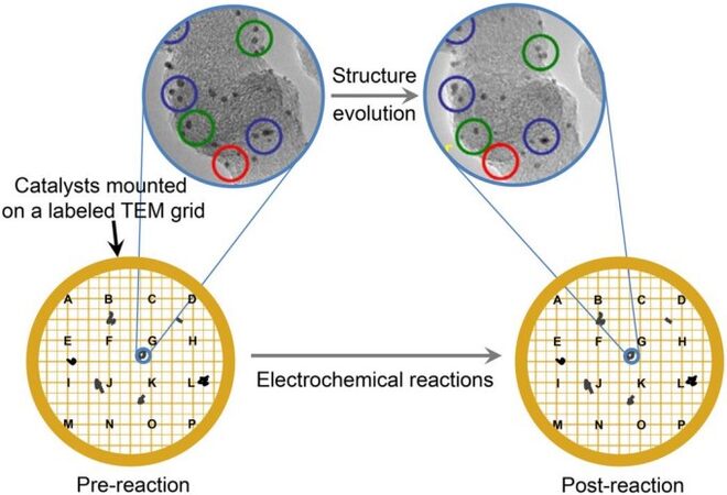
Figure 1. Schematic illustration of IL-(S)TEM using a labeled TEM grid as the electrode. The TEM grid works as the working electrode during the electrochemical tests, which can be held by an Au wire, a reverse tweezer or a glassy carbon rotating disk electrode tip using a hollow cylindrical Teflon cap. The TEM images used for illustration are adopted from Ref.[47]. TEM: Transmission electron microscopy; IL-(S)TEM: identical location (scanning) transmission electron microscopy.
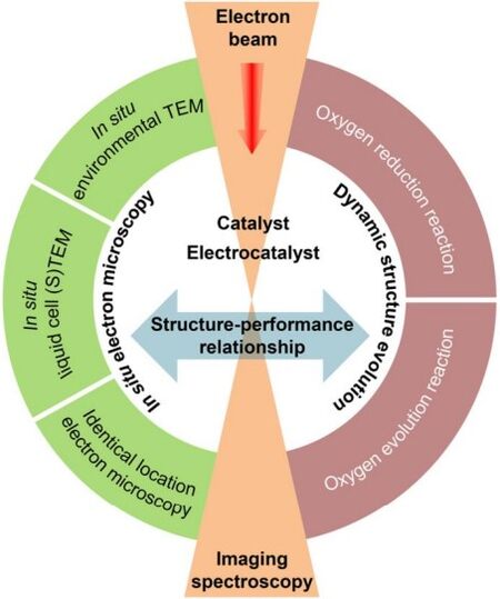
Scheme 1. Schematic illustration of in situ electron microscopy techniques used in oxygen electrocatalysis.
Compared to IL-electron microscopy, in situ LC-(S)TEM[39] exhibits a higher temporal resolution (real-time imaging) but lower spatial resolution. In LC-(S)TEM, the liquid (reaction solution or electrolyte) is encapsulated in a closed cell formed between two parallel chips and is thus physically separated from the high-vacuum environment required by the electron microscope. Consequently, the incompatible working conditions of the electrochemical reaction and (S)TEM imaging do not interfere with each other. The two chips can be assembled by wafer-bonding, gluing or simply clamping inside the holder with a spacer and O-rings in between[36]. The electrons passing through the cell windows (made of SiNx or graphene-based materials) and liquid layer are detected by the camera, detector and spectrometer and provide information on the samples deposited on the electrode inside the cell [Figure 2A and B]. An electrochemical chip comprising three microelectrodes (working electrode, counter electrode and reference electrode) can be integrated in the system to achieve simultaneous acquisition of the electrochemical performance and electron microscopy images [Figure 2C]. By observing the structure and performance of the catalysts in real time upon changes in the electrochemical conditions, the structure - performance correlations can be established, which is crucial for performing catalyst optimization via multiscale structural/compositional designs. However, the presence of liquid and the cell windows often significantly reduce the spatial resolution of the acquired images. Consequently, it is generally not possible to achieve atomic resolution in LC-(S)TEM, except in a few cases where graphene is used as the cell window material and the liquid layer is very thin[40-42]. Furthermore, the radiolysis of water caused by the electron beam irradiation produces various species, such as hydrogen and hydroxyl radicals, hydrogen, oxygen and peroxides, which inevitably alter the designed reaction environment. Compared to IL-electron microscopy, which has demonstrated applications in many electrochemical systems[43], in situ LC-(S)TEM is still in its infancy, owing to the challenge of designing liquid cells that can realize complex solid-liquid-gas triple-phase reactions and aid in achieving high-resolution images[44].
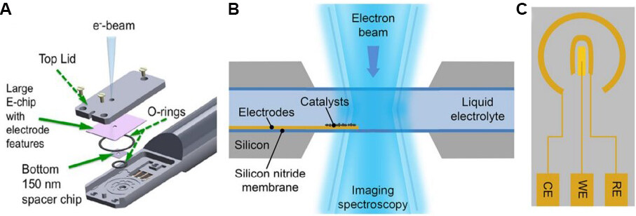
Figure 2. Schematic illustrations of (A) a commercial in situ electrochemical LC-(S)TEM sample holder[71], (B) an in situ electrochemical liquid cell placed in the optical path of TEM, and (C) an electrochemical microchip with micro-fabricated counter electrode (CE), working electrode (WE) and reference electrode (RE). The WE is made of glassy carbon, while the CE and RE are both made of Pt. The radial distance between RE and WE is ~100 μm and the radial distance between RE and CE is ~500 μm. TEM: Transmission electron microscopy; LC-(S)TEM: liquid cell (scanning) transmission electron microscopy.
In addition to IL-electron microscopy and in situ LC-(S)TEM, in situ ETEM, which allows for the introduction of various gases in the electron microscope with a limited pressure (10-5-20 mbar) around the specimen, has also been used to understand the fundamentals of reactions involving oxygen, such as the role of water vapor in the chemical OER[45]. However, in situ ETEM cannot provide a liquid-phase electrochemical environment for the catalysts. Like other electron microscopy-based characterization tools, these in situ electron microscopic techniques developed for electrochemical studies also face a challenge, i.e., the electron beam-induced structural change/damage of the specimen, which needs to be minimized via careful experimental design to obtain inherent structural information and reliable results.
IL-electron microscopy
Owing to its easy operation and high compatibility with different imaging modes, IL-electron microscopy has been used to study various electrocatalytic systems[46], including the ORR and OER.
ORR
For ORR systems, IL-electron microscopy has been mainly used to investigate the degradation (or stability) of catalysts, most of which are Pt and Pt-based nanostructures (e.g., alloy and core - shell structures). Using IL-TEM, Chorkendorff et al.[47] observed that after electrochemical potential cycling, carbon-supported Pt (Pt/C) nanoparticles became smaller in size, accompanied by the disappearance and coalescence of some particles. This observation suggests that under the electrochemical reaction conditions, the dissolution of Pt and/or the C support is the main reason for the gradual decline in the ORR performance of Pt/C. Moreover, the authors observed that the catalyst degradation is more severe at 1.2 VRHE than that at 1.1 VRHE and concluded that the degradation is not related to the potential cycling scan rate but instead heavily depends on the upper limit of the cycling window. Notably, this conclusion was drawn from a Pt/C system containing small Pt particles (2.5 nm). However, using the same IL-TEM method, Mayrhofer et al.[48] observed a much milder catalyst degradation in a Pt/C system containing larger Pt particles (~5 nm). The subsequent IL-TEM studies revealed that the metal dissolution kinetics can be affected by many factors, including the nanoparticle size[48], shape[49] and composition[50] and particle-support interaction[51-53].
In addition to Pt/C catalysts, Pt-based alloys and core - shell-structured materials are potential ORR electrocatalysts that can be used for the large-scale commercialization of fuel cells. The degradation mechanisms of these potential electrocatalysts have also been investigated extensively[54]. PtCo alloy nanomaterials are an important class of efficient ORR electrocatalysts, which have been used in commercialized fuel-cell vehicles, such as the Toyota MIRAI[55]. Hrnjic et al.[56,57] investigated the structural changes in PtCo alloy nanoparticles (as a fuel-cell electrocatalyst) during potential cycling using a combination of IL-SEM and IL-TEM. The IL-SEM analysis showed that after the catalyst activation, most particles exhibited subtle morphological changes despite the disappearance of a few particles [Figure 3A and B]. This observation suggested that the catalyst was robust under the applied mild electrochemical conditions. In a separate study using harsher electrochemical activation conditions (e.g., larger potential window or cycle numbers), obvious structural changes, including support corrosion, particle detachment and particle aggregation, in the catalyst were observed via IL-SEM[58]. Owing to its higher resolution than that of IL-SEM, IL-(S)TEM could more easily identify the detachment, coalescence, shrinkage and reshaping of the catalyst nanoparticles [Figure 3C and D]. The observed structural evolution could be attributed to the anisotropic etching/dissolution (dealloying) of the particles and atom redeposition (realloying), as revealed in the high-resolution images [Figure 3E and F]. The high-resolution IL-(S)TEM images were analyzed using fast Fourier transform recognition to separate the multiple-twinned crystal into several domains (phases 1-5 in Figure 3G). From the atomic column positions, the authors constructed a density plot, which acted as a surface evolution map to visualize the changes (appearance and disappearance) in the surface atoms during the potential cycling [Figure 3H]. These observations indicate that nanoparticle-based ORR electrocatalysts are not structurally stagnant but dynamic at the atomic scale upon exposure to the applied electrochemical conditions.
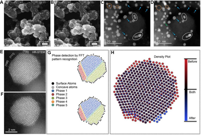
Figure 3. IL-SEM images of PtCo/C sample (A) before and (B) after potential cycling. The white circles indicate that some particles are dissolved. IL-STEM images of PtCo/C sample (C) before and (D) after potential cycling. The green arrows and orange dashed circles indicate particle detachment, white dashed circles indicate particle coalescence and blue arrows indicate particle shrinkage and reshaping. High-resolution IL-STEM images of PtCo sample (E) before and (F) after the potential cycling. (G) Atomic columns with phase detection before (top panel) and after (bottom panel) potential cycling. (H) Overlay of atomic columns before and after the reaction, showing the changes of surface atoms[56]. IL-SEM: Identical location scanning electron microscopy; STEM: scanning transmission electron microscopy.
Core - shell-structured ORR electrocatalysts have also been extensively investigated in recent decades, with typical examples including Pt-shelled nanomaterials and Pt-skinned nanocatalysts fabricated via methods such as underpotential deposition and chemical/electrochemical dealloying[21,59-62]. It is generally believed that Pt-based catalysts with this type of nanostructure are stable in electrochemical environments.
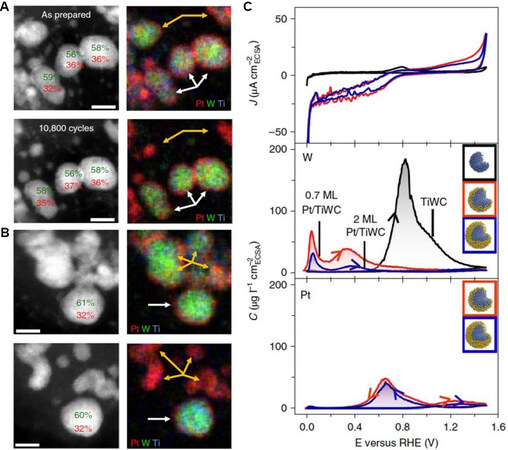
Figure 4. IL-STEM and corresponding elemental mapping images of Pt/TiWC before (upper panel) and after (bottom panel) the durability test. The white and orange arrows indicate particles with complete and incomplete Pt shells, respectively. Scale bars: (A) 5 nm and (B) 4 nm. (C) First CV curve at 2 mV/s in 0.1 M HClO4 (upper panel) and the corresponding dissolution concentration (C) profiles of W (middle panel) and Pt (bottom panel) as a function of the applied potential[63]. IL-STEM: Identical location scanning transmission electron microscopy.
OER
IL-electron microscopic techniques have also been used to investigate OER electrocatalysts. For example, Claudel et al.[66] combined IL-TEM with X-ray photoelectron spectroscopy (XPS) to investigate the degradation mechanism of various types of Ir-based OER electrocatalysts. The IL-TEM results showed the various behaviors of IrOx nanoparticles in the OER catalytic region. Some nanoparticles disappeared after the catalyst activation process, while others exhibited fragmentation, migration and coalescence. Furthermore, these behaviors were independent of the support material used. The XPS analyzes indicated that the observed morphological changes in the IrOx nanoparticles were accompanied by the evolution of the chemical oxidation states of the Ir species, i.e., Ir(0) and Ir(III) in the pristine materials were gradually converted to Ir(IV) and Ir(V), respectively. Interestingly, the authors found that compared to Ir species in other oxidation states, Ir(0) and Ir(IV) were less active for the OER. Therefore, the decay of the OER activity was attributed to the combined effect of the gradual decrease in the number of IrOx nanoparticles and the increase in the fraction of Ir(IV) in the catalyst. Lončar et al.[65] combined IL-TEM with XPS, X-ray diffraction and online inductively coupled plasma mass spectrometry to reveal that coating the Ir-based OER catalyst with a sacrificial Cu thin layer has positive effects on its activity and stability. These studies demonstrated that the combination of imaging and spectroscopy can provide a complete physical picture of the electrochemical interface to obtain a comprehensive understanding of the reaction mechanism.
Among the non-noble metal electrocatalysts developed for the OER in alkaline electrolytes, the most promising are NiFe-based materials[8,67]. Roy et al.[68] investigated the structural evolution of NiFe nanoparticles during the OER using a set of characterization approaches, including IL-SEM, IL-(HR)TEM, low-energy ion scattering (LEIS) and XPS. The authors did not observe obvious morphological changes in the NiFe nanoparticles (e.g., coalescence or dissolution) under the electrochemical OER conditions using IL-SEM [Figure 5A and D]. They claimed that IL-(HR)TEM further revealed the preserved shape and polycrystalline nature of the nanoparticles. However, the quality of the TEM images was too poor (containing limited information) to support this claim [Figure 5B and E]. The EDS line scan analysis performed on a specific nanoparticle indicated that after the electrochemical test, the oxygen content of the nanoparticle increased significantly (especially at the particle surface), whereas the Fe content decreased
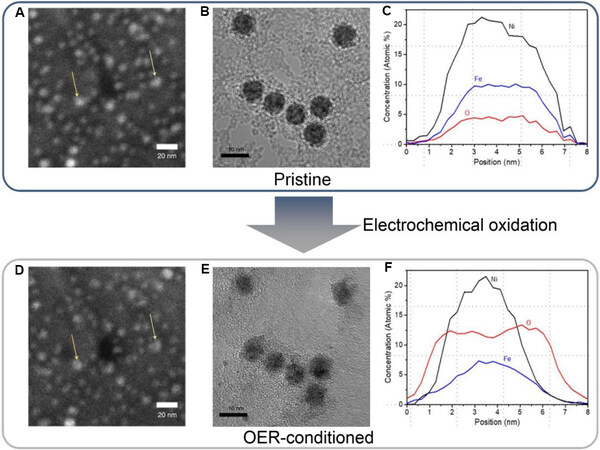
Figure 5. (A) IL-SEM image, (B) HRTEM image and (C) EDS line scan profiles of pristine NiFe nanoparticles. (D) IL-SEM image, (E) HRTEM image and (F) EDS line scan profiles of NiFe nanoparticles after electrochemical test[68]. IL-SEM: Identical location scanning electron microscopy; EDS: energy-dispersive X-ray spectroscopy.
In situ LC-(S)TEM
While IL-electron microscopy can provide high-resolution images of the initial and final states of a specimen, it is more desirable to observe the evolution of a specimen in its native states in real time during a dynamic process, such as an electrochemical reaction. For this purpose, in situ LC-(S)TEM techniques have been developed and widely used in a variety of fields, including nanomaterial nucleation and growth, corrosion science, biomolecular structure studies, bubble dynamics, radiation effects and electrochemistry[36,71]. Although liquid-phase imaging can be carried out in an open or closed cell configuration, we mainly focus on the closed cell method, where the liquid solution surrounding the samples is confined using ultrathin windows made of SiNx or graphene-based materials. Most of the reported electrochemical in situ LC-(S)TEM studies are based on this method. In this section, we present some recent studies on oxygen electrocatalysis for both the ORR and OER performed using in situ LC-(S)TEM and focus on the degradation and structural evolution of the catalysts along with the structure - performance correlations.
ORR
In situ LC-(S)TEM can provide images with temporal resolution to monitor the degradation of a catalyst. This method is particularly useful for understanding the instability of Pt-based ORR catalysts.
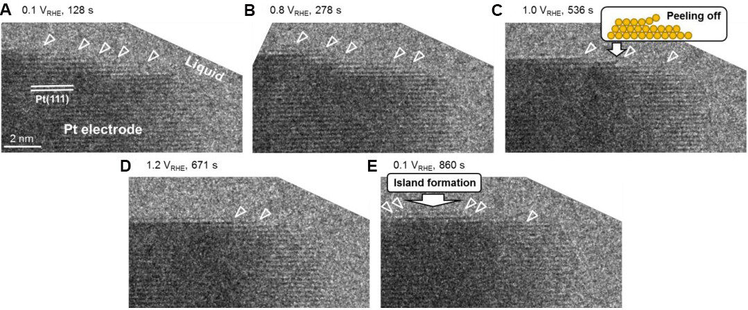
Figure 6. In situ LC-TEM observations of dynamic behavior of a Pt electrode during electrochemical potential cycling. (A-E) A set of high-resolution TEM images captured during the in situ experiment under different applied potentials. The small white triangles indicate Pt atom dissolution and redeposition[72]. LC-TEM: Liquid cell transmission electron microscopy; TEM: transmission electron microscopy.
In situ LC-(S)TEM can also shed light on the degradation of Pt-based alloy electrocatalysts, which is more complex than that of pure Pt because of the dealloying process. In a recent study, Beermann et al.[73] employed in situ electrochemical LC-(S)TEM to investigate the activation and degradation processes of carbon-supported PtNi (PtNi/C) alloy fuel-cell catalysts. They observed several real-time phenomena, including carbon support and nanoparticle motion, nanoparticle coalescence, the growth of stringy particles and atomic redeposition under electrochemical conditions, in response to the potential sweeps and holds [Figure 7]. High potential holds caused more severe structural changes in the catalysts than the cyclic potential sweeps. The most severe and sudden changes in the structure of the catalyst were identified at the transitions from the CV to the potential holds through chronoamperometry. Interestingly, the growth of the Pt-rich stringy structures via Pt redeposition was found to be driven by the reducing effects of the electron beam instead of the electrochemical reduction. This reducing agent-induced chemical redeposition of Pt is similar to the formation of pure Pt deposits inside fuel-cell membranes by the reduction of dissolved hydrogen[74]. In this reported work, a direct and precise time-resolved correlation between the applied electrochemical potential and the microstructural evolution of the catalysts was demonstrated.
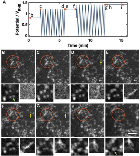
Figure 7. In situ HAADF-STEM images of PtNi alloy nanoparticle catalyst captured during in situ electrochemical liquid cell test. (A) Potential profile used in in situ experiment. The marked points correspond to the images shown below with the same labels. (B-I) Images acquired during in situ experiment under specific conditions, as marked in the potential profile. The orange circles indicate the motion and growth of nanoparticles, yellow arrows indicate atom redeposition and the green arrow in the cutouts shows the coalescence of two nanoparticles. The fields of view of the left and right cutouts are 50 and 44 nm, respectively[73]. HAADF-STEM: High-angle annular dark-field scanning transmission electron microscopy.
In another in situ LC-TEM study[75], it was found that the PtFe nanoparticles, especially those isolated in the electrolyte, exhibited a high growth tendency during the potential cycling, but the particle sizes increased abruptly rather than uniformly. When the sample was only exposed to the electron beam without applying any electrochemical potential, no significant morphological change was observed. This observation suggests that in some circumstances, the electron beam-induced effects on the structural change may be negligible and that proper control experiments are needed to confirm this. In the same system, more severe corrosion of the carbon support was observed at the areas with higher catalyst loading. These results collectively revealed that the catalyst changes unevenly in both time and space, whereas the dealloying and realloying processes of the nanocatalysts are both site and potential dependent.
OER
In situ LC-(S)TEM has also been employed to monitor the structure transformation process of OER electrocatalysts in electrochemical environments[5]. Using in situ LC-STEM, Zhu et al.[24] found that simply immersing CoSexPy (an OER pre-catalyst) in an alkaline electrolyte could result in its structural transformation to the Co(OH)2 phase, i.e., the as-prepared CoSexPy catalyst is unstable in the alkaline solution. Other in situ characterizations, including X-ray absorption fine structure spectroscopy, further confirmed the structural transformation of CoSexPy to Co (oxy)hydroxide under the OER conditions. These results indicate that Co (oxy)hydroxide, rather than CoSexPy, is the real catalytic active species in this system. Recently, Ortiz Peña et al.[76] investigated the OER behavior of Co3O4 nanoparticles using in situ electrochemical LC-STEM [Figure 8]. The chronopotentiometric curve showed a steep increase in the potential over the first 30 s, followed by a slower increase [Figure 8A]. The high-angle annular dark-field scanning transmission electron microscopy (HAADF-STEM) images acquired over a period of ~120 s showed the formation of many small crystalline nanoparticles embedded in an amorphous matrix, indicating that the surface of the Co3O4 nanocrystals was amorphized in this period. The overall area of the investigated agglomerates increased by 8% in the first 120 s and then became steady. The representative HAADF-STEM images acquired at different stages are presented in Figure 8B-D to illustrate the structural change in the catalyst over time. This shows the coexistence of crystallites and an amorphous matrix in the steady stage, i.e., the amorphization of the nanocrystals was not complete. The combination of electrochemistry and microscopy reveals that the Co3O4 nanoparticle OER electrocatalyst undergoes a rapid initial activation process to transform into an amorphous cobalt (oxy)hydroxide phase, which is electrocatalytically active toward the OER, as confirmed through other characterizations[17].
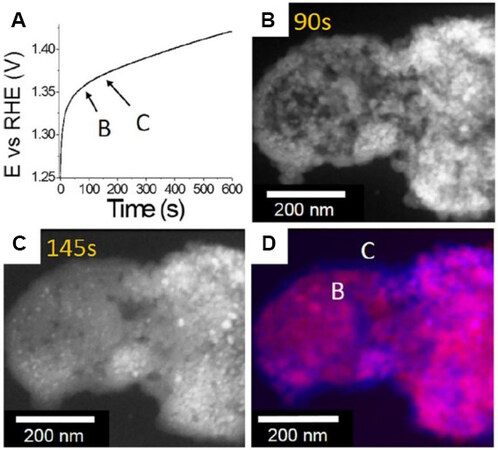
Figure 8. (A) Chronopotentiometric curve at a current density of 10 mA/cm2 in 0.1 M KOH electrolyte of Co3O4 nanocrystal catalyst during in situ electrochemical TEM experiment. (B, C) HAADF-STEM images acquired at different reaction times [(B) 90 and (C)
The electrochemical OER reaction carried out in the in situ TEM liquid cell is often violent with a large number of oxygen bubbles produced in a short time, which may influence the performance of the in situ electrochemical liquid cell and interfere with the imaging of the catalyst. To avoid this problem, a chemical OER with milder and controllable reaction kinetics can be used as an alternative for examining the electrochemical OER in the TEM liquid cell. For example, in situ LC-TEM was conducted to study the chemical OER on Mn2O3 nanocatalysts[77]. During the experiment, gas bubbles were gradually generated around the Mn2O3 nanoparticle, representing the progress of the OER process [Figure 9A]. The volume of the bubble increased in an oscillating manner with increasing reaction time, reflecting the dynamic behavior of the reaction [Figure 9B]. Moreover, a surface layer, with an oscillating thickness, was observed on the catalyst, demonstrating the reversibility of the surface reconstruction in this dynamic process [Figure 9B]. The control experiments ruled out the possibility that the observed phenomena were caused by the electron beam. Although the authors of this study[77] claimed that chemical and electrochemical OERs can induce similar structural evolutions in the catalyst, notably, the chemical OER cannot reflect the structural evolution induced by the applied electrochemical potential. For example, the valence states of the metallic active sites are dependent on the applied potential and are crucial for assessing the reaction mechanism of OERs[17]. Therefore, for investigating the intrinsic behavior of electrochemical OER catalysts, if available, in situ electrochemical LC-(S)TEM with controllable reaction kinetics is a better choice.
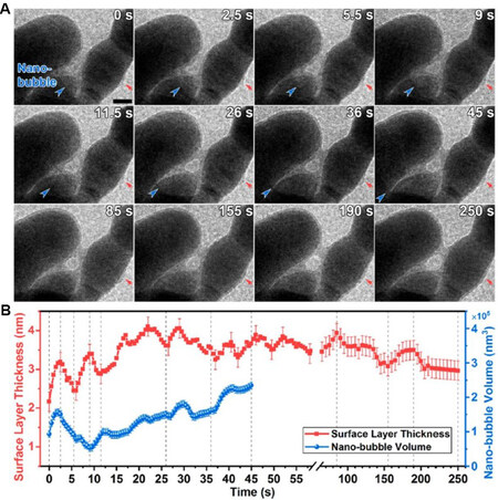
Figure 9. (A) In situ LC-TEM images showing the evolution of oxygen nanobubble (blue arrows) and surface layer (red arrows) with OER time. The scale bar represents 20 nm. (B) Corresponding evolution profiles of the surface layer thickness (red) and nanobubble volume (blue). The nanobubble volume is calculated from the boundary curvature. Error bars are ± 0.25 nm for the surface layer thickness and ± 1 × 10⁴ nm for the nanobubble volume[77]. LC-TEM: Liquid cell transmission electron microscopy; OER: oxygen evolution reaction.
In situ environmental TEM
In situ ETEM allows for real-time observations of a specimen exposed to a gas of interest with a controlled low pressure at a desired temperature. Although ETEM does not have electrochemical functions, it can be used to obtain information on the fundamental processes of electrocatalysis, such as the interactions between water and catalysts.
Using ETEM, Han et al.[45] identified the degrees of structural oscillations of various perovskite oxide-based OER catalysts in the presence of water vapor. Among the investigated perovskite oxides,
In a related study, Mierwaldt et al.[78] used in situ ETEM to study the stability of perovskite oxide
CONCLUSIONS AND PERSPECTIVES
In recent decades, we have witnessed the development of various in situ electron microscopic techniques and their important roles in the advancement of materials science and chemistry. Their applications in the study of oxygen electrocatalysis and related processes are summarized [Table 1] and discussed in this review. The main techniques used for this purpose include IL-electron microscopy and in situ LC-(S)TEM, with in situ ETEM occasionally used for specific research objectives. Owing to its easy operation, IL-electron microscopy has been widely used to identify the structural changes in specific catalyst particles during the electrocatalytic process performed outside the electron microscope and is thus considered a quasi-in situ characterization technique. In contrast, in situ LC-(S)TEM allows for real-time observation of the electrocatalyst in a liquid environment similar to its actual working conditions. This feature makes in situ LC-(S)TEM suitable for studying the evolution processes of electrocatalysts, such as the degradation mechanism of ORR catalysts during potential cycling/hold and the surface reconstruction of OER catalysts under electrochemical conditions. In addition, in situ ETEM has been primarily employed to understand the role of H2O in oxygen-related chemical reactions.
Applications of in situ electron microscopy in ORR and OER
| Reaction | Catalyst | Method | Mode | EDS/EELSa | Observations/conclusions | Ref. |
| ORR | Pt/C NPs (2.5 nm)b | IL | TEM | No | NP shrinkage, detachment and coalescence | [47] |
| ORR | PtCo/C NPs | IL | SEM/TEM/STEM | EDS | Support corrosion; particle detachment, aggregation and reshaping | [56] |
| ORR | Pt/TiWC core - shell NPs | IL | STEM | EDS | Catalyst stability depending on the completeness of the Pt shell | [63] |
| OER | IrOx NPs | IL | TEM | No | NP disappearance, fragmentation, migration and coalescence | [66] |
| OER | NiFe NPs | IL | SEM/TEM | EDS | Preserved shape and crystallinity; increased O and reduced Fe contents | [68] |
| OER | BSCF | IL | TEM/STEM | EDS/EELS | Surface structure becoming rougher and more porous | [69] |
| OER | Mn2O3 | IL | STEM | EELS | Reduced Mn valence and O coordination | [77] |
| ORR | Pt electrode | LC | TEM | No | Dissolution of Pt atom at 1.0-1.2 VRHE and their redeposition at 0.1 VRHE | [72] |
| ORR | PtNi/C NPs | LC | STEM | No | Carbon support motion; abrupt structure change of the catalyst upon the transition from CV to potential hold | [73] |
| ORR | PtFe/C | LC | TEM | No | Site- and potential-dependent atom redeposition and catalyst growth | [75] |
| OER | CoSexPy | LC | STEM | No | Phase transition of CoSexPy to Co(OH)2 in alkaline solution | [24] |
| OER | Co3O4 NPs | LC | STEM | No | Quick initial activation process generating an amorphous surface structure | [76] |
| OER | Mn2O3 | LC | TEM | No | Visualization of the OER process through bubble formation | [77] |
| OER | BSCF | In situ ETEM | TEM | EELS | Structural oscillation in the presence of H2O vapor and electron beam | [45] |
| OER | PrCaMnOx | In situ ETEM | TEM | EELS | Formation of a dynamic surface layer | [78] |
Like any other characterization technique, these in situ electron microscopic techniques have their own limitations. IL-electron microscopy and in situ ETEM do not incorporate liquid electrolytes or exert electrochemical potential in the electron microscope and therefore real-state images of the electrocatalyst cannot be obtained using these methods. Moreover, IL-electron microscopy cannot even provide time-resolved information for the catalyst. Although in situ LC-(S)TEM can provide a liquid-phase electrochemical environment for the specimen, it has two main limitations, i.e., the inevitable electron beam effect and poor spatial resolution (nm-scale rather than atomic resolution in most cases). The electron beam irradiation may cause structural damage in the specimen or induce radiolysis effects to influence the environment of the reaction. Using a flowing liquid cell can refresh the solution around the catalyst during in situ (S)TEM experiments to reduce the contamination caused by the electron beam-induced water radiolysis and (electro)chemical reactions. Alternatively, minimizing the electron dose used for imaging would also reduce the side effects associated with the electron beam irradiation. However, a low electron dose would result in a poor signal-to-noise ratio in the image. Consequently, other strategies are required to improve the image quality, including the use of a highly sensitive camera or detector and the development of advanced image processing techniques[80-82].
The poor spatial resolution of LC-(S)TEM images originates from the multiple scattering of electrons by the cell window and liquid layer. Reducing the thickness of the liquid layer can improve the spatial resolution; however, this approach may lead to results that deviate from those of the bulk. For example, nanoparticle diffusion in a confined liquid cell was reported to be several orders more sluggish than that in a bulk solution because of the increased liquid viscosity[83]. Moreover, nanoparticles can be adsorbed on the SiNx window, which has a nonuniform surface charge distribution caused by the radiolysis of water[84]. Therefore, the liquid layer thickness needs to be optimized according to the system to be investigated. Furthermore, reducing the thickness of the cell window also helps to improve the resolution. For instance, using graphene as the window material could realize atomic-resolution imaging[85] and nm-resolution elemental mapping in LC-(S)TEM[40]. However, current graphene-based TEM liquid cells are difficult to fabricate (very low success rate) and cannot be combined with electrochemistry accessories for electrocatalytic research. Thus, ultrathin and robust liquid cells, equipped with electrochemical functions, are in high demand for the further advancement of in situ LC-(S)TEM.
There are other challenges in the application of in situ electron microscopy to the study of oxygen electrocatalysis. First, most in situ (S)TEM studies are performed using the conventional imaging modes that produce two-dimensional projection images. (S)TEM tomography can provide 3D structural/morphological information regarding the catalyst; however, performing tomography with a liquid cell is a considerable challenge, because the liquid cell severely limits the tilting angles of the specimen holder. Second, it is difficult to perform EDS and EELS analyzes with LC-(S)TEM, because the thick window and liquid layer block most of the X-ray photons and inelastically scattered electrons emitted from the sample’s region of interest. To perform EDS/EELS analyzes with LC-(S)TEM, the liquid cells need to be rationally designed to enhance the collection efficiency of the required signals. The latest advances in chip fabrication and TEM holder design have significantly increased the effective solid-angle range of the detector, thereby increasing the X-ray collection efficiency. Additionally, the invention of large solid-angle X-ray detectors and high-sensitivity EELS spectrometers have enabled outstanding signal detection, with a higher efficiency than before[86-88]. In addition, the high electron dose required to generate sufficient secondary signals for EDS or EELS, which is generally several orders of magnitude higher than that needed to produce annular dark-field images[89], might produce a large number of gas bubbles in the liquid, thereby affecting the imaging process. A possible solution to this issue is to use a flowing liquid cell. Third, there is a lack of effective methods for automatically and accurately identifying the structural changes in the image series that are acquired in situ. New image processing and image recognition technologies, possibly based on machine learning, are necessary to bridge this gap. The ultimate goal is to achieve the automatic correlation between catalyst structure and catalytic performance with the assistance of new computing algorithms. Lastly, we should realize that the information that in situ (S)TEM can provide is limited and thus must be supplemented by other characterization techniques and first-principles calculations to obtain a complete understanding of the system under study.
DECLARATIONS
Authors’ contributionsConceived and designed the manuscript: Wu ZP, Han Y
Drafted and revised the manuscript: Wu ZP, Zhang H, Chen C, Li G, Han Y
Availability of data and materialsNot applicable.
Financial support and sponsorshipThis work was supported by the AMPM CCF fund (FCC/1/1972-43-01), granted to Han Y by the King Abdullah University of Science and Technology.
Conflicts of interestAll authors declared that there are no conflicts of interest.
Ethical approval and consent to participateNot applicable.
Consent for publicationNot applicable.
Copyright© The author(s) 2022.
REFERENCES
2. Kibsgaard J, Chorkendorff I. Considerations for the scaling-up of water splitting catalysts. Nat Energy 2019;4:430-3.
3. Shao M, Chang Q, Dodelet JP, Chenitz R. Recent advances in electrocatalysts for oxygen reduction reaction. Chem Rev 2016;116:3594-657.
4. Xiao F, Wang YC, Wu ZP, et al. Recent advances in electrocatalysts for proton exchange membrane fuel cells and alkaline membrane fuel cells. Adv Mater 2021;33:e2006292.
5. Wu ZP, Lu XF, Zang S, Lou XW. Non-noble-metal-based electrocatalysts toward the oxygen evolution reaction. Adv Funct Mater 2020;30:1910274.
6. Tian X, Zhao X, Su YQ, et al. Engineering bunched Pt-Ni alloy nanocages for efficient oxygen reduction in practical fuel cells. Science 2019;366:850-6.
7. Lei Q, Zhu H, Song K, et al. Investigating the origin of enhanced C2+ selectivity in oxide-/hydroxide-derived copper electrodes during CO2 electroreduction. J Am Chem Soc 2020;142:4213-22.
8. Wu ZP, Zhang H, Zuo S, et al. Manipulating the local coordination and electronic structures for efficient electrocatalytic oxygen evolution. Adv Mater 2021;33:e2103004.
9. Wu ZP, Caracciolo DT, Maswadeh Y, et al. Alloying-realloying enabled high durability for Pt-Pd-3d-transition metal nanoparticle fuel cell catalysts. Nat Commun 2021;12:859.
10. Chong L, Wen J, Kubal J, et al. Ultralow-loading platinum-cobalt fuel cell catalysts derived from imidazolate frameworks. Science 2018;362:1276-81.
11. Kong Z, Maswadeh Y, Vargas JA, et al. Origin of high activity and durability of twisty nanowire alloy catalysts under oxygen reduction and fuel cell operating conditions. J Am Chem Soc 2020;142:1287-99.
12. Wu ZP, Shan S, Xie Z, et al. Revealing the role of phase structures of bimetallic nanocatalysts in the oxygen reduction reaction. ACS Catal 2018;8:11302-13.
13. Huang J, Yang T, Zhao K, Chen S, Huang Q, Han Y. Copper-comprising nanocrystals as well-defined electrocatalysts to advance electrochemical CO2 reduction. J Energy Chem 2021;62:71-102.
14. Shan J, Ye C, Chen S, et al. Short-range ordered iridium single atoms integrated into cobalt oxide spinel structure for highly efficient electrocatalytic water oxidation. J Am Chem Soc 2021;143:5201-11.
15. Wu ZP, Zhong CJ. Pd-based electrocatalysts for oxygen reduction and ethanol oxidation reactions: some recent insights into structures and mechanisms. J Electrochem 2021;27:144-56.
16. Zheng X, Zhang B, De Luna P, et al. Theory-driven design of high-valence metal sites for water oxidation confirmed using in situ soft X-ray absorption. Nat Chem 2018;10:149-54.
17. Wu T, Sun S, Song J, et al. Iron-facilitated dynamic active-site generation on spinel CoAl2O4 with self-termination of surface reconstruction for water oxidation. Nat Catal 2019;2:763-72.
18. Rao RR, Kolb MJ, Giordano L, et al. Operando identification of site-dependent water oxidation activity on ruthenium dioxide single-crystal surfaces. Nat Catal 2020;3:516-25.
19. Wu Z, Zhang M, Jiang H, Zhong CJ, Chen Y, Wang L. Competitive C-C and C-H bond scission in the ethanol oxidation reaction on Cu(100) and the effect of an alkaline environment. Phys Chem Chem Phys 2017;19:15444-53.
20. Wu ZP, Miao B, Hopkins E, et al. Poisonous species in complete ethanol oxidation reaction on palladium catalysts. J Phys Chem C 2019;123:20853-68.
21. Chen C, Kang Y, Huo Z, et al. Highly crystalline multimetallic nanoframes with three-dimensional electrocatalytic surfaces. Science 2014;343:1339-43.
22. Wan G, Freeland JW, Kloppenburg J, et al. Amorphization mechanism of SrIrO3 electrocatalyst: how oxygen redox initiates ionic diffusion and structural reorganization. Sci Adv 2021;7:eabc7323.
23. Liu Z, Zhao Z, Peng B, Duan X, Huang Y. Beyond extended surfaces: understanding the oxygen reduction reaction on nanocatalysts. J Am Chem Soc 2020;142:17812-27.
24. Zhu Y, Chen H, Hsu C, et al. Operando unraveling of the structural and chemical stability of P-substituted CoSe2 electrocatalysts toward hydrogen and oxygen evolution reactions in alkaline electrolyte. ACS Energy Lett 2019;4:987-94.
25. Zhu Y, Wang J, Chu H, Chu Y, Chen HM. In situ/operando studies for designing next-generation electrocatalysts. ACS Energy Lett 2020;5:1281-91.
26. Li J, Gong J. Operando characterization techniques for electrocatalysis. Energy Environ Sci 2020;13:3748-79.
27. Yang Y, Xiong Y, Zeng R, et al. Operando methods in electrocatalysis. ACS Catal 2021;11:1136-78.
28. Dong J, Zhang X, Briega-martos V, et al. In situ Raman spectroscopic evidence for oxygen reduction reaction intermediates at platinum single-crystal surfaces. Nat Energy 2019;4:60-7.
29. Cheng W, Zhao X, Su H, et al. Lattice-strained metal–organic-framework arrays for bifunctional oxygen electrocatalysis. Nat Energy 2019;4:115-22.
30. Zhao S, Tan C, He C, et al. Structural transformation of highly active metal–organic framework electrocatalysts during the oxygen evolution reaction. Nat Energy 2020;5:881-90.
31. Fan Z, Zhang L, Baumann D, et al. In situ transmission electron microscopy for energy materials and devices. Adv Mater 2019;31:e1900608.
32. Hwang S, Chen X, Zhou G, Su D. In situ transmission electron microscopy on energy-related catalysis. Adv Energy Mater 2020;10:1902105.
33. Li J, Johnson G, Zhang S, Su D. In situ transmission electron microscopy for energy applications. Joule 2019;3:4-8.
34. Zhang C, Firestein KL, Fernando JFS, Siriwardena D, von Treifeldt JE, Golberg D. Recent progress of in situ transmission electron microscopy for energy materials. Adv Mater 2020;32:e1904094.
35. Pu S, Gong C, Robertson AW. Liquid cell transmission electron microscopy and its applications. R Soc Open Sci 2020;7:191204.
36. Ross FM. Opportunities and challenges in liquid cell electron microscopy. Science 2015;350:aaa9886.
37. Mayrhofer KJ, Meier JC, Ashton SJ, et al. Fuel cell catalyst degradation on the nanoscale. Electrochem Commun 2008;10:1144-7.
38. Arenz M, Zana A. Fuel cell catalyst degradation: identical location electron microscopy and related methods. Nano Energy 2016;29:299-313.
39. Hodnik N, Dehm G, Mayrhofer KJ. Importance and challenges of electrochemical in situ liquid cell electron microscopy for energy conversion research. Acc Chem Res 2016;49:2015-22.
40. Kelly DJ, Zhou M, Clark N, et al. Nanometer resolution elemental mapping in graphene-based TEM liquid cells. Nano Lett 2018;18:1168-74.
41. Park J, Koo K, Noh N, et al. Graphene liquid cell electron microscopy: progress, applications, and perspectives. ACS Nano 2021;15:288-308.
42. Hauwiller MR, Ye X, Jones MR, et al. Tracking the effects of ligands on oxidative etching of gold nanorods in graphene liquid cell electron microscopy. ACS Nano 2020;14:10239-50.
43. Wang Q, Gao Y, Ma Z, et al. Supported ionic liquid phase-boosted highly active and durable electrocatalysts towards hydrogen evolution reaction in acidic electrolyte. J Energy Chem 2021;54:342-51.
44. Velasco-Velez JJ, Mom RV, Sandoval-Diaz LE, et al. Revealing the active phase of copper during the electroreduction of CO2 in aqueous electrolyte by correlating in situ X-ray spectroscopy and in situ electron microscopy. ACS Energy Lett 2020;5:2106-11.
45. Han B, Stoerzinger KA, Tileli V, Gamalski AD, Stach EA, Shao-Horn Y. Nanoscale structural oscillations in perovskite oxides induced by oxygen evolution. Nat Mater 2017;16:121-6.
46. Hodnik N, Cherevko S. Spot the difference at the nanoscale: identical location electron microscopy in electrocatalysis. Curr Opin Electrochem 2019;15:73-82.
47. Perez-alonso FJ, Elkjær CF, Shim SS, Abrams BL, Stephens IE, Chorkendorff I. Identical locations transmission electron microscopy study of Pt/C electrocatalyst degradation during oxygen reduction reaction. J Power Sources 2011;196:6085-91.
48. Mayrhofer KJ, Ashton SJ, Meier JC, Wiberg GK, Hanzlik M, Arenz M. Non-destructive transmission electron microscopy study of catalyst degradation under electrochemical treatment. J Power Sources 2008;185:734-9.
49. Arán-Ais RM, Yu Y, Hovden R, et al. Identical location transmission electron microscopy imaging of site-selective Pt nanocatalysts: electrochemical activation and surface disordering. J Am Chem Soc 2015;137:14992-8.
50. da Silva GC, Fernandes MR, Ticianelli EA. Activity and stability of Pt/IrO2 bifunctional materials as catalysts for the oxygen evolution/reduction reactions. ACS Catal 2018;8:2081-92.
51. Souza NE, Bott-neto JL, Rocha TA, et al. Support modification in Pt/C electrocatalysts for durability increase: a degradation study assisted by identical location transmission electron microscopy. Electrochimica Acta 2018;265:523-31.
52. Sakthivel M, Drillet J. An extensive study about influence of the carbon support morphology on Pt activity and stability for oxygen reduction reaction. Appl Catal B: Environ 2018;231:62-72.
53. Schonvogel D, Hülstede J, Wagner P, et al. Stability of Pt nanoparticles on alternative carbon supports for oxygen reduction reaction. J Electrochem Soc 2017;164:F995-F1004.
54. Wu ZP, Shan S, Zang SQ, Zhong CJ. Dynamic core-shell and alloy structures of multimetallic nanomaterials and their catalytic synergies. Acc Chem Res 2020;53:2913-24.
55. Yoshida T, Kojima K. Toyota MIRAI fuel cell vehicle and progress toward a future hydrogen society. Interface magazine 2015;24:45-9.
56. Hrnjic A, Kamšek AR, Pavlišič A, et al. Observing, tracking and analysing electrochemically induced atomic-scale structural changes of an individual Pt-Co nanoparticle as a fuel cell electrocatalyst by combining modified floating electrode and identical location electron microscopy. Electrochimica Acta 2021;388:138513.
57. Hrnjić A, Ruiz-zepeda F, Gaberšček M, et al. Modified floating electrode apparatus for advanced characterization of oxygen reduction reaction electrocatalysts. J Electrochem Soc 2020;167:166501.
58. Zorko M, Jozinović B, Bele M, Hodnik N, Gaberšček M. SEM method for direct visual tracking of nanoscale morphological changes of platinum based electrocatalysts on fixed locations upon electrochemical or thermal treatments. Ultramicroscopy 2014;140:44-50.
59. Cai B, Hübner R, Sasaki K, et al. Core-shell structuring of pure metallic aerogels towards highly efficient platinum utilization for the oxygen reduction reaction. Angew Chem Int Ed Engl 2018;57:2963-6.
60. Strasser P, Koh S, Anniyev T, et al. Lattice-strain control of the activity in dealloyed core-shell fuel cell catalysts. Nat Chem 2010;2:454-60.
61. Kang Y, Snyder J, Chi M, et al. Multimetallic core/interlayer/shell nanostructures as advanced electrocatalysts. Nano Lett 2014;14:6361-7.
62. Wu ZP, Shan S, Wang S, et al. . Multimetallic catalysts and electrocatalysts: dynamic core-shell nanostructures. In: Yamashita H, Li H, editors. Core-shell and yolk-shell nanocatalysts. Singapore: Springer; 2021. p. 61-82.
63. Göhl D, Garg A, Paciok P, et al. Engineering stable electrocatalysts by synergistic stabilization between carbide cores and Pt shells. Nat Mater 2020;19:287-91.
64. Lyu X, Jia Y, Mao X, et al. Gradient-concentration design of stable core-shell nanostructure for acidic oxygen reduction electrocatalysis. Adv Mater 2020;32:e2003493.
65. Lončar A, Escalera-López D, Ruiz-Zepeda F, et al. Sacrificial Cu layer mediated the formation of an active and stable supported iridium oxygen evolution reaction electrocatalyst. ACS Catal 2021;11:12510-9.
66. Claudel F, Dubau L, Berthomé G, et al. Degradation mechanisms of oxygen evolution reaction electrocatalysts: a combined identical-location transmission electron microscopy and X-ray photoelectron spectroscopy study. ACS Catal 2019;9:4688-98.
67. Yang H, Gong L, Wang H, et al. Preparation of nickel-iron hydroxides by microorganism corrosion for efficient oxygen evolution. Nat Commun 2020;11:5075.
68. Roy C, Sebok B, Scott SB, et al. Impact of nanoparticle size and lattice oxygen on water oxidation on NiFeOxHy. Nat Catal 2018;1:820-9.
69. Shen TH, Spillane L, Vavra J, et al. Oxygen evolution reaction in Ba0.5Sr0.5Co0.8Fe0.2O3-δ aided by intrinsic Co/Fe spinel-like surface. J Am Chem Soc 2020;142:15876-83.
70. Quast T, Varhade S, Saddeler S, et al. Single particle nanoelectrochemistry reveals the catalytic oxygen evolution reaction activity of Co3O4 nanocubes. Angew Chem Int Ed Engl 2021;60:23444-50.
71. Mehdi BL, Qian J, Nasybulin E, et al. Observation and quantification of nanoscale processes in lithium batteries by operando electrochemical (S)TEM. Nano Lett 2015;15:2168-73.
72. Nagashima S, Ikai T, Sasaki Y, et al. Atomic-level observation of electrochemical platinum dissolution and redeposition. Nano Lett 2019;19:7000-5.
73. Beermann V, Holtz ME, Padgett E, de Araujo JF, Muller DA, Strasser P. Real-time imaging of activation and degradation of carbon supported octahedral Pt–Ni alloy fuel cell catalysts at the nanoscale using in situ electrochemical liquid cell STEM. Energy Environ Sci 2019;12:2476-85.
74. Holby EF, Sheng W, Shao-horn Y, Morgan D. Pt nanoparticle stability in PEM fuel cells: influence of particle size distribution and crossover hydrogen. Energy Environ Sci 2009;2:865.
75. Zhu G, Prabhudev S, Yang J, Gabardo CM, Botton GA, Soleymani L. In situ liquid cell TEM study of morphological evolution and degradation of Pt–Fe nanocatalysts during potential cycling. J Phys Chem C 2014;118:22111-9.
76. Ortiz Peña N, Ihiawakrim D, Han M, et al. Morphological and structural evolution of Co3O4 nanoparticles revealed by in situ electrochemical transmission electron microscopy during electrocatalytic water oxidation. ACS Nano 2019;13:11372-81.
77. Zhao G, Yao Y, Lu W, et al. Direct observation of oxygen evolution and surface restructuring on Mn2O3 nanocatalysts using in situ and ex situ transmission electron microscopy. Nano Lett 2021;21:7012-20.
78. Mierwaldt D, Roddatis V, Risch M, et al. Environmental TEM investigation of electrochemical stability of perovskite and ruddlesden-popper type manganite oxygen evolution catalysts. Adv Sustainable Syst 2017;1:1700109.
79. Ronge E, Lindner J, Ross U, et al. Atom surface dynamics of manganese oxide under oxygen evolution reaction-like conditions studied by in situ environmental transmission electron microscopy. J Phys Chem C 2021;125:5037-47.
80. Zhu Y, Ciston J, Zheng B, et al. Unravelling surface and interfacial structures of a metal-organic framework by transmission electron microscopy. Nat Mater 2017;16:532-6.
81. Zhang D, Zhu Y, Liu L, et al. Atomic-resolution transmission electron microscopy of electron beam-sensitive crystalline materials. Science 2018;359:675-9.
82. Liu L, Chen Z, Wang J, et al. Imaging defects and their evolution in a metal-organic framework at sub-unit-cell resolution. Nat Chem 2019;11:622-8.
83. Verch A, Pfaff M, de Jonge N. Exceptionally slow movement of gold nanoparticles at a solid/liquid interface investigated by scanning transmission electron microscopy. Langmuir 2015;31:6956-64.
84. Chee SW, Baraissov Z, Loh ND, Matsudaira PT, Mirsaidov U. Desorption-mediated motion of nanoparticles at the liquid–solid interface. J Phys Chem C 2016;120:20462-70.
85. Yuk JM, Park J, Ercius P, et al. High-resolution EM of colloidal nanocrystal growth using graphene liquid cells. Science 2012;336:61-4.
86. Maigné A, Wolf M. Low-dose electron energy-loss spectroscopy using electron counting direct detectors. Microscopy (Oxf) 2018;67:i86-97.
87. Zaluzec NJ, Burke MG, Haigh SJ, Kulzick MA. X-ray energy-dispersive spectrometry during in situ liquid cell studies using an analytical electron microscope. Microsc Microanal 2014;20:323-9.
88. Ercius P, Hachtel JA, Klie RF. Chemical and bonding analysis of liquids using liquid cell electron microscopy. MRS Bull 2020;45:761-8.
Cite This Article
Export citation file: BibTeX | RIS
OAE Style
Wu ZP, Zhang H, Chen C, Li G, Han Y. Applications of in situ electron microscopy in oxygen electrocatalysis. Microstructures 2022;2:2022002. http://dx.doi.org/10.20517/microstructures.2021.12
AMA Style
Wu ZP, Zhang H, Chen C, Li G, Han Y. Applications of in situ electron microscopy in oxygen electrocatalysis. Microstructures. 2022; 2(1): 2022002. http://dx.doi.org/10.20517/microstructures.2021.12
Chicago/Turabian Style
Wu, Zhi-Peng, Hui Zhang, Cailing Chen, Guanxing Li, Yu Han. 2022. "Applications of in situ electron microscopy in oxygen electrocatalysis" Microstructures. 2, no.1: 2022002. http://dx.doi.org/10.20517/microstructures.2021.12
ACS Style
Wu, Z.P.; Zhang H.; Chen C.; Li G.; Han Y. Applications of in situ electron microscopy in oxygen electrocatalysis. Microstructures. 2022, 2, 2022002. http://dx.doi.org/10.20517/microstructures.2021.12
About This Article
Copyright

Data & Comments
Data


 Cite This Article 19 clicks

 Like This Article 0
likes
Like This Article 0
likes


Comments
Comments must be written in English. Spam, offensive content, impersonation, and private information will not be permitted. If any comment is reported and identified as inappropriate content by OAE staff, the comment will be removed without notice. If you have any queries or need any help, please contact us at support@oaepublish.com.