
Effects of processing parameters on a β-solidifying TiAl alloy fabricated by laser-based additive manufacturing

Abstract
β-solidifying TiAl alloys are considered as promising candidate materials for high-temperature structural applications. Laser-based additive manufacturing (LAM) enables the fabrication of components with geometrical complexity in near-net shape, leading to time and feedstock savings. In this study, a gas-atomized Ti-44Al-4Nb-1Mo-1Cr powder is used as a feedstock material for LAM. However, the LAM of TiAl alloys remains a challenge due to serious cracking during the printing process. To minimize the cracking, the optimization of the LAM processing parameters is essential. Hence, the effects of the LAM processing parameters on the cracking susceptibility and microstructure are studied here. Our experimental results show that the cracking susceptibility can be mitigated by increasing the laser power. Accordingly, the microstructure transforms from the dominating α2 grains to a near-lamellar microstructure with an increment in laser power, leading to a reduction in microhardness, even though it is still higher than that of its as-cast counterparts. It is concluded that changes in the laser power can directly tailor the microstructure, phase composition and microhardness of LAM-fabricated TiAl alloys.
Keywords
INTRODUCTION
Intermetallic TiAl alloys are considered as excellent candidates for replacing Ni- and Ti-based alloys in aerospace applications due to their attractive properties, including low densities (3.8-4.2 g/cm3), which are around half those of Ni-based alloys (8-9 g/cm3)[1], high specific strength and creep resistance at elevated temperatures and better oxidation resistance than conventional Ti alloys, particularly at 600-800 °C[2,3]. After several years of fundamental research, novel β-solidifying TiAl alloys have been developed, which offer opportunities for weight reduction and an operating temperature of increase up to 850 °C[4,5]. These TiAl alloys are characterized by a high content of β-stabilizing elements, such as Nb and Mo, and composed of complex multi-phases[5], including the existence of a high volume fraction of β phase or its ordered counterparts, β0[6].
In contrast to conventional TiAl alloys, which solidify via a peritectic solidification path (i.e.,
Additive manufacturing (AM) enables the fabrication of near-net-shape components with complex geometries at higher efficiency and lower costs, compared with conventional manufacturing technologies[11,12]. Thus, AM has significant potential for manufacturing TiAl alloys and is of technical and economic interest. So far, several works have demonstrated that electron beam melting (EBM) is capable of directly making TiAl near-net-shape parts[13-15]. However, significant Al loss and inhomogeneous microstructures were found in TiAl alloys produced from EBM[16,17], which are inevitably detrimental to the mechanical properties of the alloys. Compared to EBM, laser-based additive manufacturing (LAM) exhibits superior dimensional and surface finish qualities and lower machine costs due to the use of a finer laser beam and feedstock powder[18]. However, the major problem encountered during LAM is cracking[19]. In LAM, the high energy input and small heat-affected zone result in a high cooling rate (104-106 K/s) and the generation of high thermal stress[20], which brittle TiAl alloys cannot accommodate, leading to cracking and distortion. Due to the nature of the additive layers, the LAM process experiences a complex thermal history involving melting, subsequent solidification and numerous lower temperature reheating cycles, which lead to very specific microstructures[21]. Most published works have shown that the adjustment of processing parameters can alleviate the internal defects and tailor the microstructure[22,23], since the properties of TiAl alloys are strongly dependent on the microstructure[24-26].
To incorporate advanced manufacturing technology using novel materials, knowledge of processing-related properties is of great importance. Thus, in this study, the microstructural characterization of a β-solidifying TiAl alloy fabricated by LAM with different laser powers is presented. The influence of laser power on the internal defects, microstructural features and microhardness are evaluated to better understand the effects of processing parameters on the LAM-based β-solidifying TiAl alloy.
EXPERIMENTAL PROCEDURE
The β-solidifying TiAl alloy with nominal composition Ti-44Al-4Nb-1Mo-1Cr (at.%) was used as the feedstock for LAM in the present study. The pre-alloyed spherical powder with particle sizes ranging from 47.8 to 130.0 μm was supplied by Xi’an Sailong Metal Materials Co., Ltd. The powder morphology is depicted in Figure 1A. Prior to printing, the powder was dried at 80 °C for 2 h under a vacuum to remove moisture.
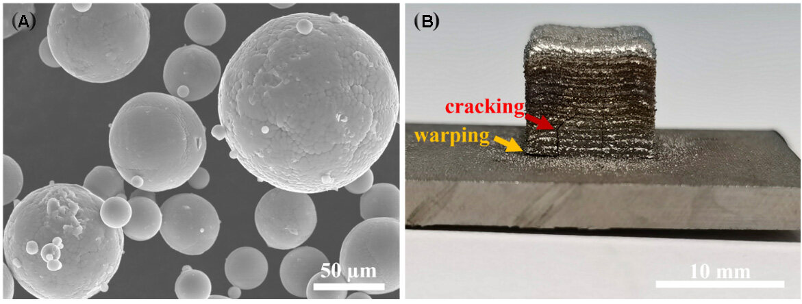
Figure 1. (A) Pre-alloyed Ti-44Al-4Nb-1Mo-1Cr powder morphology. (B) Representative image showing macrographs of as-printed specimens built with a laser power of 320 W.
An Optomec LENS 450 machine was used to print the TiAl alloy samples on Ti-6Al-4V substrates. The laser power was altered while other parameters were kept constant, as listed in Table 1. Basically, the LENS 450 machine uses a 1064 nm wavelength Nd:YAG laser, a four-nozzle coaxial powder feeder, a controlled environment chamber and a motion control system. During the printing process, a high-powered laser beam is focused onto the substrate while the alloy powders are injected into the substrate from the powder delivery nozzles[27]. Upon interaction with the energy source, the powder was melted almost instantly, creating melt pools and then solidifying rapidly as the energy source moved away[11]. Successive layers are sequentially deposited to build the designed geometry. The printing process was conducted in an Ar-purged processing chamber where an oxygen content of less than 10 ppm was maintained to avoid oxidation. The cubic parts (10 mm × 10 mm × 10 mm) were built for further metallographic characterization. The printing scheme used in this study was a bi-directional scan in the X-Y plane without rotation between the layers.
Design of LAM processing parameters for β-solidifying TiAl alloy
| Parameters | Value |
| Laser power (W) | 230, 260, 290, 320, 350 and 380 |
| Laser scan speed (mm/min) | 650 |
| Powder feeder rate (rpm) | 4 |
| Layer thickness (inches) | 0.01 |
| Hatching spacing (inches) | 0.015 |
| Argon | 99.999% purity |
The as-printed samples were sectioned along the longitudinal planes, which were parallel to the building direction, followed by mechanically grinding and polishing and chemically etching with Keller’s reagent
The Vickers microhardness was measured on a microhardness tester (HXD-1000TMC, Shanghai Taiming Optical Instrument Corporation, China) with a 300 g load held for 15 s. At least ten measurements were taken for each sample.
RESULTS AND DISCUSSION
LAM-based β-solidifying TiAl alloy
The scanning electron microscope-energy dispersive X-ray spectroscopy (SEM-EDS) measured elemental concentrations of the pre-alloyed powder and the as-printed samples fabricated with different laser power inputs are listed in Table 2. Negligible changes in the chemical composition of the as-printed alloys after LAM were detected in comparison to the original pre-alloyed powder. Hence, the chemical composition of the as-printed samples was not affected by the LAM process in this study.
EDS analysis results showing elemental concentrations for pre-alloyed powder used and as-printed samples
| Sample | Ti (wt.%) | Al (wt.%) | Nb (wt.%) | Mo (wt.%) | Cr (wt.%) |
| Powder | 58.18 | 29.93 | 8.23 | 2.33 | 1.35 |
| 230 W | 59.23 | 30.11 | 7.69 | 1.61 | 1.37 |
| 260 W | 57.32 | 31.79 | 7.91 | 1.67 | 1.32 |
| 290 W | 58.21 | 30.96 | 7.77 | 1.79 | 1.29 |
| 320 W | 58.15 | 30.90 | 7.89 | 1.73 | 1.34 |
| 350 W | 57.94 | 31.02 | 8.02 | 1.71 | 1.31 |
| 380 W | 58.09 | 31.21 | 7.65 | 1.61 | 1.34 |
The typical appearance of the LAM-fabricated β-solidifying TiAl samples with dimensions of 10 mm ×
The relationship between cracking susceptibility and laser power was further investigated. All as-printed samples produced with different laser powers contain cracks, as indicated by the red arrows in Figure 2. At a very low laser power of 230 W, the long and deep cracks originated from the edge of the sample and propagated along the building direction of the as-printed sample, as shown in Figure 2A. However, increasing the laser from 230 to 380 W led to alleviation of the cracking in the as-printed samples, as shown in Figure 2B-F. Only short cracks were observed as the laser increased to 380 W [Figure 2F]. The cracking in LAM is ascribed to the generation of thermal stress, which is caused by a large thermal gradient during laser heating. The extent of cracking is expected to be severe because brittle TiAl alloys cannot accommodate such high stress through deformation. The energy density input is defined as the energy per unit area, which is calculated by[30]:

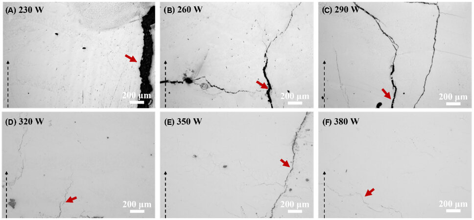
Figure 2. Cross-section views of as-printed samples with different laser powers: (A) 230; (B) 260; (C) 290; (D) 320; (E) 350; (F) 380 W. Internal defects are observed on the ground and polished samples. Dashed arrows indicate the build direction.
where Ρ is the laser power, υ is the scanning speed and D is the laser beam diameter. The cooling rate during the printing process is dependent on the energy input based on Rosenthal’s three-dimensional solution[31], which can be expressed as follows:

where k is the thermal conductivity of the material and T0 is the substrate temperature. The cooling rate is inversely proportional to the energy density. A higher energy density can increase the width of the melt pool’s contact with the substrate, thereby producing a larger melt pool that can maintain fluidity for a long period and prevent a high cooling rate[25]. Therefore, the mitigation of the cracking is attributed to the lower cooling rate resulting from the higher energy input.
Microstructure and phase analysis
XRD was used to determine the phase constituents of the LAM-based samples fabricated with different laser powers. To better understand the phase transformation during the solidification process, a calculated Ti-Al phase diagram is provided in Figure 3B. The XRD patterns obtained across the building direction confirm the existence of three phases. The results, as presented in Figure 3A, reveal that the diffraction peaks belong to the α2, γ and β0 phases in the as-printed samples. There is a slight deviation at a few peaks, which is ascribed to the change in the size of the tested specimens and the lattice imperfection caused by the high cooling rate and complex thermal history during the LAM process. It is noteworthy that more diffraction peaks of the γ phase could be detected with increasing laser power. This result illustrates that the content of the γ phase gradually increases with enhanced laser power.
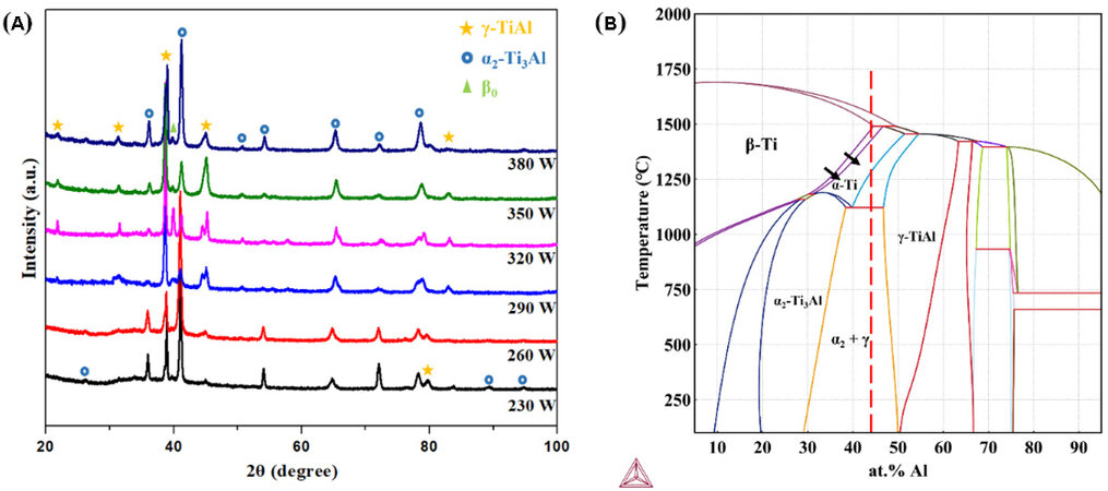
Figure 3. (A) XRD patterns of as-printed samples fabricated by different laser powers of 230, 260, 290, 320, 350 and 380 W. (B) Phase diagram for Ti-Al alloy (at.%). The arrows indicate the movement of the phase boundaries for β-stabilizing element additions. XRD: X-ray diffraction.
The general microstructure appears to be refined in comparison to the conventionally processed TiAl alloys[4] due to the higher cooling rate. Different microstructures could be observed for the as-printed alloys depending on the laser power. The microstructures of the as-printed TiAl alloys manufactured with low laser power consist of mostly α2 phases [Figure 4A and B], which are not typical for TiAl alloys. These are related to the high cooling rates, which suppress the formation of lamellar, because the diffusion-controlled phase transformation of α → α2 + γ is sensitive to the cooling rate[32]. For the as-printed specimens fabricated using laser powers of 230 and 260 W, the cooling rate is high enough that the α → α2 transformation took place. The lamellar colonies could be recognized in some regions with the intermediate laser power of
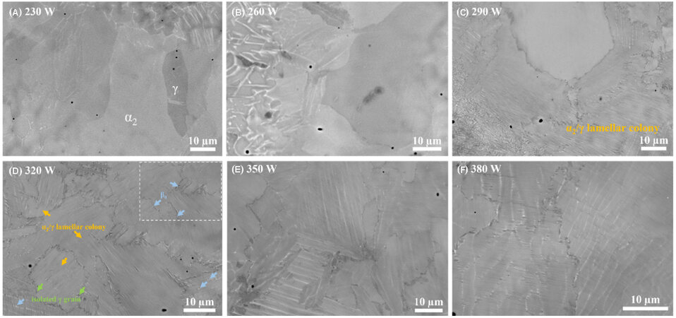
Figure 4. SEM-BSE images showing the effect of laser power on microstructures of LAM-based TiAl alloys: (A) 230; (B) 260; (C) 290; (D) 320; (E) 350; (F) 380 W. The insert shows the details at higher magnification. SEM: Scanning electron microscope.
The equiaxed γ (dark) grains and β0 (bright) phase decorate the α2/γ colony boundaries, as indicated by the green and blue arrows, respectively, in Figure 4D. Since the strong β-stabilizing elements of Nb and Mo concentrated in the primary β phase at high temperature and were hard to diffuse during a shorter time, the primary β phase could not completely decompose into the α phase. Part of the primary β phase would be retained and directly ordered to the β0 phase upon the further cooling process, which was distributed along the grain boundary, as indicated in Figure 4D. Moreover, it can be found that the β0 phase can be identified within the lamellar colonies, which is consistent with the previous works of
To understand the formation of the microstructure, the Ti-Al binary phase diagram is provided, as shown in Figure 3B, which is calculated by the Thermo-Calc analysis. However, in the case of the β-solidifying TiAl alloy, due to the existence of β-stabilizing elements, Nb, Mo and Cr in this study shift the single β-Ti phase boundaries to a higher Al content regime, thus expanding the β-Ti phase field, as indicated by the black arrow in Figure 3B. Since the β-solidifying TiAl alloy contains sufficient β-stabilizing elements, the solidification pathway would be more complicated than the conventional casting of the TiAl alloy[33]. Therefore, the solidification pathway in our study takes place completely via the β phase following the sequence: L → L + β → β → β + α → β + α + γ → β + α2 + γ → β0 + α2/γ + γ. The α2 and β0 phases are ordered α and β phases, respectively, at low temperatures[35]. After solidification and upon further cooling, the disordered hexagonal α nucleates following the Burgers orientation relationship as (0001)α||{110}β and
The lamellar colony consists of α2-Ti3Al and γ-TiAl, which stems from the solid-state phase transformation. The ultrafine and closely packed lamellae, which are alternating α2-Ti3Al and γ-TiAl, are further characterized by TEM in detail, as shown in Figure 5. According to the TEM bright-field images in Figure 5A, fine lamellar with an average lamellar spacing on a nanoscale (44 nm) is presented, while the lamellar spacing is 1-2 μm in the case of conventionally processed TiAl alloys[41]. The insert selected area electron diffraction proved the Blackburn orientation relationship between the α2/γ lamellae, which is (111)γ||(0001)α2 and
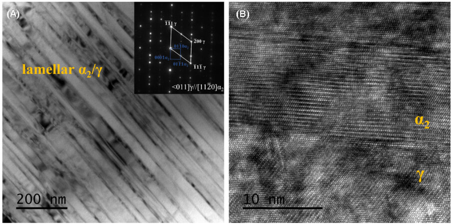
Figure 5. Structural details of lamellar colony characterized via TEM, showing an ultrafine lamellar structure. (A) TEM bright-field image showing the lamellae. The insert SADP showing the Blackburn orientation relationship followed by α2/γ lamellae. (B) HRTEM image presenting α2 and γ plates.
Grain features
EBSD was introduced and conducted on the representative LAM-based TiAl alloy samples fabricated by different laser powers of 230, 290 and 350 W to characterize the influence of laser power on grain features, which are relevant to the energy density inputs[24,45]. The EBSD phase map of the as-printed TiAl alloy fabricated at 230 W, as shown in Figure 6A, demonstrates that the microstructure is dominated by the α2 phase (green) and a small amount of γ (red) and β0 (yellow). The content of the γ phase increases with the reduction of the α2 phase with increasing laser power. This phenomenon is ascribed to the competition between α → α + γ → α2 + γ transformation and the direct-ordering α → α2 reaction[46]. According to
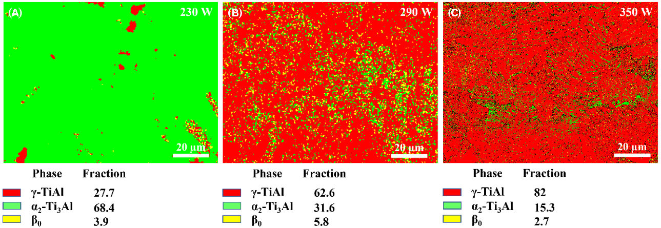
Figure 6. Phase maps from EBSD analysis showing the phase distribution and phase fraction of typical as-printed TiAl alloys fabricated by different laser powers: (A) 230; (B) 290; (C) 350 W. Red, green and yellow represent the γ, α2 and β0 phases, respectively. EBSD: Electron backscattered diffraction.
EBSD inverse pole figure maps are presented for each specimen in Figure 7A-C. The different colors correspond to different orientations in grains with respect to the crystal lattice. A multi-orientation of grains is distributed along the building direction. To measure the grain size, the representative band contrast maps, which provide higher contrast for counting, are shown in Figure 7D-F. Moreover, the average grain sizes of the as-presented samples were calculated to be 10.68, 14.50 and 25.77 μm, respectively. The grain size increases with increasing laser power. Figure 8 presents the grain misorientation angle map. The grain boundaries were categorized as low-angle grain boundaries (< 15°, LAGBs) and high-angle grain boundaries (> 15°, HAGBs). Obviously, the as-printed alloys are dominated by HAGBs with percentages of 92.12%, 97.68% and 98.54%, respectively. HAGBs are generally caused by dynamic recrystallization[4]. Because LAM is a layer-wise addition process, this process involves several reheating cycles due to successive laser track and laser deposition. The previously solidified layers would be inevitably reheated when making a new layer. This phenomenon is similar to the annealing heat treatment in which recrystallization would take place[47]. Furthermore, the content of HAGBs is observed to increase with increasing laser power. An increase in laser power will result in a lower solidification rate and provide a longer time for remelting and recrystallization. Therefore, the grain features could be tailored by varying the applied laser power.
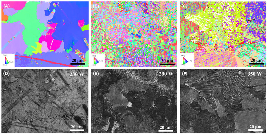
Figure 7. EBSD inverse pole figure maps and image quality maps showing grain orientation and distribution of as-printed TiAl alloys fabricated by different laser powers of (A) and (D) 230, (B) and (E) 290 and (C) and (F) 350 W. EBSD: Electron backscattered diffraction.
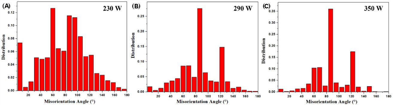
Figure 8. Grain orientation maps of as-printed TiAl samples fabricated by different laser powers of (A) 230, (B) 290 and (C) 350 W.
Microhardness
To investigate the role of the processing parameters in determining the mechanical properties, microhardness measurements were conducted on the LAM-based TiAl alloys fabricated with different laser powers. The results are presented in Figure 9. The microhardness of the samples varies in the range of 475.1 to 534.8 HV, much higher than the corresponding as-cast counterparts reported in the literature, which are generally less than 351 HV[34]. In addition, it is evident that the microhardness is reduced with increasing laser power from 230 to 380 W. The reduction of the microhardness is mainly attributed to the following two reasons. At lower laser power, the phase composition is dominated by the α2 phase. The α2 phase was found to be harder than the γ phase and lamellar colony[4]. Therefore, the reduction in the α2 phase decreases the microhardness. Furthermore, according to the Hall-Petch relation equation, the hardness of a material is dependent on its grain size. Thus, the hardness-grain size relation is described as[48]:

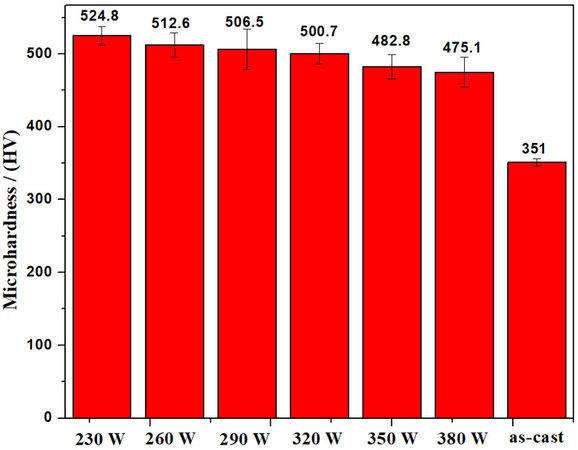
Figure 9. Microhardness of as-printed samples fabricated by different laser powers in comparison with the as-cast counterparts.
where H0 and KH are constants. As discussed above, the grain size generally increases with increasing laser power, thus leading to the reduction in microhardness. In addition, due to the rapid cooling rate during the printing process, the LAM-based specimens exhibited refined grain size than the casting counterparts, contributing to the increase of microhardness in the as-printed state.
CONCLUSION
In this study, a β-solidifying TiAl alloy, Ti-44Al-4Nb-1Mo-1Cr, was fabricated by LAM with different laser powers. Due to the complex thermal history during the LAM process, the as-printed intermetallic TiAl alloy samples showed susceptibility to cracking. Our work proved that the cracking problem could be mitigated by increasing the incident laser power to control the cooling rate. Nevertheless, the optimized process parameters could not suppress it totally. Therefore, future work is necessary to explore effective methods to achieve crack-free specimens. Several methods are worthy of investigation. For example, the optimized processing parameters combined with an external heating source can slow down the cooling rate and prevent cracking, or incorporation with hot isostatic pressing is possible to heal short cracks. Moreover, in the present study, the operation parameter (laser power) has a significant effect on the microstructural evolution of the as-printed samples. The microstructure is dominated by brittle α2 phase with lower laser power, while the microstructure exhibits a near-lamellar structure with an ultrafine lamellar spacing as the laser power increases to 380 W. The as-printed specimens all exhibited higher microhardness compared with that fabricated by casting.
DECLARATIONS
AcknowledgmentsThe authors would like to acknowledge the technical assistance of SUSTech Core Research Facilities.
Authors’ contributionsContributed to conception and design of the study, data collection and analysis, manuscript drafting:
Contributed to the material characterization: Dong Y
Helped with material preparation: Chen H
Contributed to mechanism explanation: Zhou Y
Supervised the overall project: Zhang MX
Supervised the overall project: Yan M
Availability of data and materialsNot applicable.
Financial support and sponsorshipThis study is supported by Research and Development Program Project in Key Areas of Guangdong Province (Grants No. 2019B090907001 and 2019B010943001), Natural Science Foundation of Guangdong Province (2020A1515011373), the Central Guidance on Local: Construction of regional innovation system - Cross Regional R & D cooperation projects (20221ZDH04054) and ARC DP program (DP210103162).
Conflicts of interestAll authors declared that there are no conflicts of interest.
Ethical approval and consent to participateNot applicable.
Consent for publicationNot applicable.
Copyright© The Author(s) 2022.
REFERENCES
1. Perrut M, Caron P, Thomas M, Couret A. High temperature materials for aerospace applications: Ni-based superalloys and γ-TiAl alloys. Comptes Rendus Physique 2018;19:657-71.
2. Dimiduk DM. Gamma titanium aluminide alloys-an assessment within the competition of aerospace structural materials. Mater Sci Eng 1999;263:281-8.
4. Niu HZ, Chen YY, Xiao SL, Xu LJ. Microstructure evolution and mechanical properties of a novel beta γ-TiAl alloy. Intermetallics 2012;31:225-31.
5. Clemens H, Mayer S. Design, processing, microstructure, properties, and applications of advanced intermetallic TiAl alloys. Adv Eng Mater 2013;15:191-215.
6. Kartavykh A, Asnis E, Piskun N, Statkevich I, Gorshenkov M, Korotitskiy A. A promising microstructure/deformability adjustment of β-stabilized γ-TiAl intermetallics. Mater Lett 2016;162:180-4.
7. Clemens H, Wallgram W, Kremmer S, Güther V, Otto A, Bartels A. Design of novel β-solidifying TiAl alloys with adjustable β/B2-phase fraction and excellent hot-workability. Adv Eng Mater 2008;10:707-13.
8. Mayer S, Erdely P, Fischer FD, et al. Intermetallic β-solidifying γ-TiAl based alloys - from fundamental research to application: intermetallic β-solidifying γ-TiAl based alloys. Adv Eng Mater 2017;19:1600735.
9. Kothari K, Radhakrishnan R, Wereley NM. Advances in gamma titanium aluminides and their manufacturing techniques. Prog Aerosp Sci 2012;55:1-16.
10. Thomas M, Raviart JL, Popoff F. Cast and PM processing development in gamma aluminides. Intermetallics 2005;13:944-51.
11. Sahasrabudhe H, Bose S, Bandyopadhyay A. Laser-based additive manufacturing processes. Adva Laser Mater Proc 2018:507-39.
12. Li S, Li J, Jiang Z, et al. Controlling the columnar-to-equiaxed transition during directed energy deposition of inconel 625. Addit Manufact 2022;57:102958.
13. Narayana P, Li C, Kim S, et al. High strength and ductility of electron beam melted β stabilized γ-TiAl alloy at 800 °C. Mater Sci Eng 2019;756:41-5.
14. Wartbichler R, Clemens H, Mayer S. Electron beam melting of a β-solidifying intermetallic titanium aluminide alloy. Adv Eng Mater 2019;21:1900800.
15. Baudana G, Biamino S, Klöden B, et al. Electron beam melting of Ti-48Al-2Nb-0.7Cr-0.3Si: feasibility investigation. Intermetallics 2016;73:43-9.
16. Lin B, Chen W, Yang Y, Wu F, Li Z. Anisotropy of microstructure and tensile properties of Ti-48Al-2Cr-2Nb fabricated by electron beam melting. J Alloys Compd 2020;830:154684.
17. Schwerdtfeger J, Körner C. Selective electron beam melting of Ti-48Al-2Nb-2Cr: microstructure and aluminium loss. Intermetallics 2014;49:29-35.
18. Bhavar PKV, Patil V, Khot S, Gujar K, Singh R. A review on powder bed fusion technology of metal additive manufacturing, In 4th international conference and exhibition on additive manufacturing technologies-AM-2014, 1-2 Septeber 2014, Banglore, India.
19. Sharman A, Hughes J, Ridgway K. Characterisation of titanium aluminide components manufactured by laser metal deposition. Intermetallics 2018;93:89-92.
20. Yan Z, Liu W, Tang Z, et al. Review on thermal analysis in laser-based additive manufacturing. Opt Laser Technol 2018;106:427-41.
21. Zheng B, Zhou Y, Smugeresky J, Schoenung J, Lavernia E. Thermal behavior and microstructural evolution during laser deposition with laser-engineered net shaping: part I. numerical calculations. Metall Mat Trans A 2008;39:2228-36.
22. Srivastava D, Chang ITH, Loretto MH. The effect of process parameters and heat treatment on the microstructure of direct laser fabricated TiAl alloy samples. Intermetallics 2001;9:1003-13.
23. Balla VK, Das M, Mohammad A, Al-ahmari AM. Additive manufacturing of γ-TiAl: processing, microstructure, and properties: additive manufacturing of γ-TiAl: processing. Adv Eng Mater 2016;18:1208-15.
24. Li W, Liu J, Zhou Y, et al. Effect of laser scanning speed on a Ti-45Al-2Cr-5Nb alloy processed by selective laser melting: microstructure, phase and mechanical properties. J Alloys Compd 2016;688:626-36.
25. Löber L, Schimansky FP, Kühn U, Pyczak F, Eckert J. Selective laser melting of a beta-solidifying TNM-B1 titanium aluminide alloy. J Mater Proc Technol 2014;214:1852-60.
26. Biamino S, Penna A, Ackelid U, et al. Electron beam melting of Ti-48Al-2Cr-2Nb alloy: microstructure and mechanical properties investigation. Intermetallics 2011;19:776-81.
27. Huang SH, Liu P, Mokasdar A, Hou L. Additive manufacturing and its societal impact: a literature review. Int J Adv Manuf Technol 2013;67:1191-203.
28. Zhou Y, Li W, Wang D, et al. Selective laser melting enabled additive manufacturing of Ti-22Al-25Nb intermetallic: excellent combination of strength and ductility, and unique microstructural features associated. Acta Mater 2019;173:117-29.
29. Brion DA, Shen M, Pattinson SW. Automated recognition and correction of warp deformation in extrusion additive manufacturing. Addit Manuf 2022;56:102838.
30. Abdulrahman KO, Akinlabi ET, Mahamood RM. Characteristics of laser metal deposited titanium aluminide. Mater Res Express 2019;6:046504.
31. Liu W, Dupont JN. Fabrication of carbide-particle-reinforced titanium aluminide-matrix composites by laser-engineered net shaping. Metall Mater Trans A 2004;35:1133-40.
32. Li W, Liu J, Wen S, Wei Q, Yan C, Shi Y. Crystal orientation, crystallographic texture and phase evolution in the Ti-45Al-2Cr-5Nb alloy processed by selective laser melting. Maters Charact 2016;113:125-33.
33. Xu H, Li X, Xing W, Shu L, Ma Y, Liu K. Solidification pathway and phase transformation behavior in a beta-solidified gamma-TiAl based alloy. J Mater Sci Technol 2019;35:2652-7.
34. Schwaighofer E, Clemens H, Mayer S, et al. Microstructural design and mechanical properties of a cast and heat-treated intermetallic multi-phase γ-TiAl based alloy. Intermetallics 2014;44:128-40.
35. Ramanujan R. Phase transformations in γ based titanium aluminides. Int Mater Rev 2000;45:217-40.
36. Yang G, Ren W, Liu Y, et al. Effect of pre-deformation in the β phase field on the microstructure and texture of the α phase in a boron-added β-solidifying TiAl alloy. J Alloys Compd 2018;742:304-11.
37. Hu D, Huang A, Wu X. On the massive phase transformation regime in TiAl alloys: the alloying effect on massive/lamellar competition. Intermetallics 2007;15:327-32.
38. Sankaran A, Bouzy E, Humbert M, Hazotte A. Variant selection during nucleation and growth of γ-massive phase in TiAl-based intermetallic alloys. Acta Materialia 2009;57:1230-42.
39. Sun YQ. Surface relief and the displacive transformation to the lamellar microstructure in TiAl. Philosopy Magaz Lett 1998;78:297-305.
40. Chaturvedi M, Xu Q, Richards N. Development of crack-free welds in a TiAl-based alloy. J Mater Proc Technol 2001;118:74-8.
41. Srivastava D, Chang I, Loretto M. The optimisation of processing parameters and characterisation of microstructure of direct laser fabricated TiAl alloy components. Mater Design 2000;21:425-33.
42. Denquin A, Naka S. Phase transformation mechanisms involved in two-phase TiAl-based alloys-I. lambellar structure formation. Acta Materialia 1996;44:343-52.
43. Kastenhuber M, Rashkova B, Clemens H, Mayer S. Enhancement of creep properties and microstructural stability of intermetallic β-solidifying γ-TiAl based alloys. Intermetallics 2015;63:19-26.
44. Bernal D, Chamorro X, Hurtado I, Madariaga I. Evolution of lamellar microstructures in a cast TNM alloy modified with boron through single-step heat treatments. Intermetallics 2020;124:106842.
45. Song B, Dong S, Zhang B, Liao H, Coddet C. Effects of processing parameters on microstructure and mechanical property of selective laser melted Ti6Al4V. Mater Design 2012;35:120-5.
46. Berteaux O, Popoff F, Thomas M. An experimental assessment of the effects of heat treatment on the microstructure of Ti-47Al-2Cr-2Nb powder compacts. Metall Mat Trans A 2008;39:2281-96.
47. Li M, Wu X, Yang Y, et al. TiAl/RGO (reduced graphene oxide) bulk composites with refined microstructure and enhanced nanohardness fabricated by selective laser melting (SLM). Mater Charact 2018;143:197-205.
Cite This Article
Export citation file: BibTeX | RIS
OAE Style
Huang D, Dong Y, Chen H, Zhou Y, Zhang MX, Yan M. Effects of processing parameters on a β-solidifying TiAl alloy fabricated by laser-based additive manufacturing. Microstructures 2022;2:2022019. http://dx.doi.org/10.20517/microstructures.2022.17
AMA Style
Huang D, Dong Y, Chen H, Zhou Y, Zhang MX, Yan M. Effects of processing parameters on a β-solidifying TiAl alloy fabricated by laser-based additive manufacturing. Microstructures. 2022; 2(4): 2022019. http://dx.doi.org/10.20517/microstructures.2022.17
Chicago/Turabian Style
Huang, Danni, Yangping Dong, Hancong Chen, Yinghao Zhou, Ming-Xing Zhang, Ming Yan. 2022. "Effects of processing parameters on a β-solidifying TiAl alloy fabricated by laser-based additive manufacturing" Microstructures. 2, no.4: 2022019. http://dx.doi.org/10.20517/microstructures.2022.17
ACS Style
Huang, D.; Dong Y.; Chen H.; Zhou Y.; Zhang M.X.; Yan M. Effects of processing parameters on a β-solidifying TiAl alloy fabricated by laser-based additive manufacturing. Microstructures. 2022, 2, 2022019. http://dx.doi.org/10.20517/microstructures.2022.17
About This Article
Copyright

Data & Comments
Data


 Cite This Article 13 clicks

 Like This Article 1
likes
Like This Article 1
likes


Comments
Comments must be written in English. Spam, offensive content, impersonation, and private information will not be permitted. If any comment is reported and identified as inappropriate content by OAE staff, the comment will be removed without notice. If you have any queries or need any help, please contact us at support@oaepublish.com.