
Low neutron cross-section FeCrVTiNi based high-entropy alloys: design, additive manufacturing and characterization
 0
0
Abstract
The development of high-entropy alloys (HEAs) based on the novel alloying concept of multi-principal components presents opportunities for achieving new materials with desired properties for increasingly demanding applications. In this study, a low neutron cross-section FeCrVTiNi-based HEA was developed for potential nuclear applications. A face-centred cubic (FCC) HEA with the nominal composition of FeCr0.4V0.3Ti0.2Ni1.3 is proposed based on the empirical thermodynamic models and the CALculation of PHAse diagrams (CALPHAD) calculation. Verifications of the predictions were performed, including the additive manufacturing of the proposal material and a range of microstructural characterizations and mechanical property tests. Consistent with the prediction, the as-fabricated HEA consists of a dominant FCC phase and minor Ni3Ti precipitates. Moreover, significant chemical segregation in the alloy, as predicted by the CALPHAD modelling, was observed experimentally in the produced dendritic microstructure showing the enrichment of Ni and Ti elements in the interdendritic regions and the segregation of Cr and V elements in the dendritic cores. Heterogenous mechanical properties, including microhardness and tensile strengths, were observed along the building direction of the additively manufactured HEA. The various solid solution strengthening effects, due to the chemical segregation (in particular Cr and V elements) during solidification, are identified as significant contributing factors to the observed mechanical heterogeneity. Our study provides useful knowledge for the design and additive manufacturing of compositionally complex HEAs and their composition-microstructure-mechanical property correlation.
Keywords
INTRODUCTION
Developing structural materials that can withstand the harsh service environments of current and next-generation nuclear reactors, including high-radiation dose, high-temperature and corrosion, remains to be one of the main challenges in achieving their safe and economic operations. The structural materials and components for nuclear applications need to have a combination of low neutron cross-section, high radiation and corrosion resistance, good high-temperature mechanical performance, as well as favorable dimensional stability and resistance to swelling, flaking and thermal fatigue[1,2]. Conventional alloys, including steels, nickel alloys, and zirconium alloys, have been extensively used in the nuclear industry for a variety of applications such as steam generators, pressure vessels, fuel assemblies and other reactor in-core components because of their compatibility and durability[3]. However, they suffer from the problems of stress corrosion cracking, precipitation embrittlement and void swelling under reactor operational environments, which limit their service lifetime[3-5]. Therefore, it is important to design and develop new alloys outside the paradigms of conventional alloys to advance next-generation nuclear technology applications.
High-entropy alloys (HEAs) have been emerging as a new class of materials since 2004[6], which normally contain four to five principal elements and form a simple face-centred cubic (FCC), or body-centred cubic (BCC) single-phase solid-solution or a dual-phase of FCC + BCC. They have attracted significant interest in scientific and industrial communities because of their unique alloy design concept and promising properties under a range of environmental conditions[7-9]. In particular, stimulated by the promising radiation resistance of HEAs essentially resulting from the severe lattice distortion, sluggish diffusion and chemical disorder in the materials[10-12], research efforts have been devoted to developing particular HEA systems (reduced activation and/or low neutron cross-section compositions) with potentials for nuclear applications. For example, Ayyagari et al.[13] developed the reduced activation Ta-Ti-V-Zr-X (X = Hf or W) HEAs of BCC structure by a combined experimental and molecular dynamics approach. King et al.[14] proposed the Nb-Ti-V-Zr based HEAs, which consist of the dominant BCC phase as the high-temperature, low neutron cross-section materials for nuclear applications. Although the BCC phase normally contributes to improving the material’s strength and forms the constitutions of refractory HEAs compatible for high-temperature applications, single-phase BCC HEAs are shown to have larger irradiation-induced volume swelling than FCC HEAs[15], which are in contrast to the case of conventional alloys[16]. As such, the development of low neutron cross-section, FCC HEAs with a good balance of strength and ductility together with superior dimensional stability under irradiation environments would be technologically important for future nuclear applications.
A comprehensive evaluation of the materials’ properties (including the mechanical performance and radiation damage resistance) is necessary before certifying the candidate materials for nuclear applications. However, the first step is to achieve the design and manufacturing of the materials (especially for new materials) and establish an understanding on the relationship of the processing-microstructure-mechanical performance. The present work is towards the end of this first step. In this work, we target at developing FCC HEAs based on a pentanary FeCrVTiNi system with the constituting elements of relatively low neutron cross-sections (approximately 2.5-6 barn), as tabulated in Table 1[17,18]. We agree that future studies looking into the comprehensive materials properties (such as creep and radiation damage resistance) are needed. A combination of the currently known empirical calculation models for predicting the formation and stability of single-phase HEAs[19] and the CALculation of PHAse Diagrams (CALPHAD) approach with the Thermo-Calc program was utilized in the alloy design. To verify the predictions, a selected HEA of predicted FCC structure with a nominal composition of FeCr0.4V0.3Ti0.2Ni1.3 was produced experimentally using a new powder-bed arc additive manufacturing (PAAM) approach established in our previous work[20]. This additive manufacturing approach is advantageous for its higher production rate and capability of fabricating components with complex geometries compared with conventional processes of arc melting or casting. However, due to its inherent characteristics of relatively high cooling rate and complex thermal history associated with the layer-by-layer depositions[20-22], the produced microstructure and resultant properties of additively manufactured materials are often distinctive from those of the counterparts by conventional processes. Hence, the microstructure of the PAAM produced HEAs was characterized and correlated with the mechanical properties. The results show that a dominant FCC microstructure with minor Ni3Ti precipitates was achieved for the designed HEA material. Additionally, a significant local compositional fluctuation exists along the building direction of the produced HEA, which is believed to result from the chemical segregation that occurred during the PAAM process and is responsible for the observed variations of the mechanical properties along the building direction.
MATERIALS AND METHODS
Materials design
The formation and stability of the solid-solution phases in HEAs are determined by their thermodynamics[23]. There have been several empirical models[18,23-26] predicting the crystalline structure and stability of the solid-solution phases in HEAs based on various thermophysical parameters, including the entropy of mixing (ΔSmix), enthalpy of mixing (ΔHmix), atomic size differences (δ), valence electron concentration (VEC), Pauling electronegativity difference (Δχ) and the Ω parameter which is defined in the following:
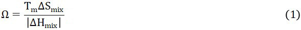
where Tm is the melting temperature of the alloys estimated from the rule of mixtures of all elements. The entropy of mixing (ΔSmix) of the multi-component HEAs is defined as:
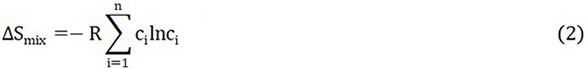
where R is the ideal gas constant and ci is the atomic percentage of the ith element. It has been well-accepted that the entropy of mixing (ΔSmix) is not the only factor that determines the solid-solution single-phase formation in the HEAs[27,28]. Hence, the other empirical parameters are also considered in the present work. The enthalpy of mixing (ΔHmix) for a system is calculated as:
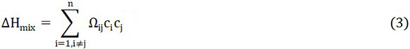
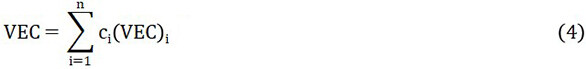
where Ωij = 4ΔHAB, and ΔHAB is the mixing enthalpy of binary AB alloys in the liquid state determined using Miedema’s model[29]. The VEC of the HEA system is calculated as:
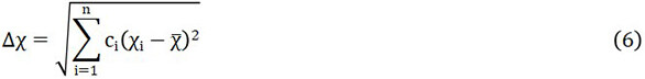
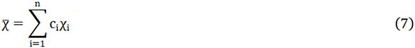
where (VEC)i is the VEC for the ith element. The atomic size difference (δ) is defined as:
where  , with ci and ri being the atomic percentage and the atomic radius of the ith element, respectively. The Pauling electronegativity difference (Δχ) parameter is defined as:
where χi is the Pauling electronegativity of the ith element.
According to previous studies[18,23-26], a single FCC solid-solution phase tends to form in a HEA while the empirical parameters of this alloy system fall into specific ranges of 0 ≤ δ ≤ 8.5, -22 ≤ ΔHmix ≤ 7 kJ/mol, 11 ≤ ΔSmix ≤ 19.5, VEC > 8 and Ω ≥ 1.1. We have determined a range of compositions based on the FeCrVTiNi system, which meet these criteria. Details of the determined compositions and their parameter values can be found in Supplementary Table 1. Moreover, we considered that in the investigated HEA system, the Ni-Ti has a low enthalpy of mixing which means their intermetallic is likely to form in the alloy system. In order to minimize the potential formation of Ni-Ti intermetallics in the alloys, we selected a HEA composition of FeCr0.4V0.3Ti0.2Ni1.3 with the lowest Ni content among the designed 57 potential compositions for further investigations in this work. The choice of a low Ni content in the designed alloy is also beneficial for reducing its potential activation after irradiation. The calculated empirical parameters for the selected FeCr0.4V0.3Ti0.2Ni1.3 alloy composition are listed in Table 2. To verify the alloy design based on the empirical models, CALPHAD calculations of the FeCr0.4V0.3Ti0.2Ni1.3 system using the Thermal-Calc® software were further performed. As the Ni content is the highest in this composition, we simply took this alloy as a Ni-based alloy, and the preliminary CALPHAD calculations were based on the TCNI10 thermodynamic and MOBNI4 mobility databases for Ni-alloys.
Solid-solution phase stability parameter (Ω), the entropy of mixing (ΔSmix), enthalpy of mixing (ΔHmix), VEC, atomic size difference (δ), Pauling electronegativity difference (Δχ) for the designed FeCr0.4V0.3Ti0.2Ni1.3 HEA
| Parameters | Ω | ΔSmix | ΔHmix | VEC | δ | Δχ |
| FeCr0.4V0.3Ti0.2Ni1.3 | 2.54 | 11.51 | -7.226 | 8.03 | 4.35 | 0.12 |
Additive manufacturing and characterization
To verify the alloy design experimentally, a new PAAM approach was used to produce the
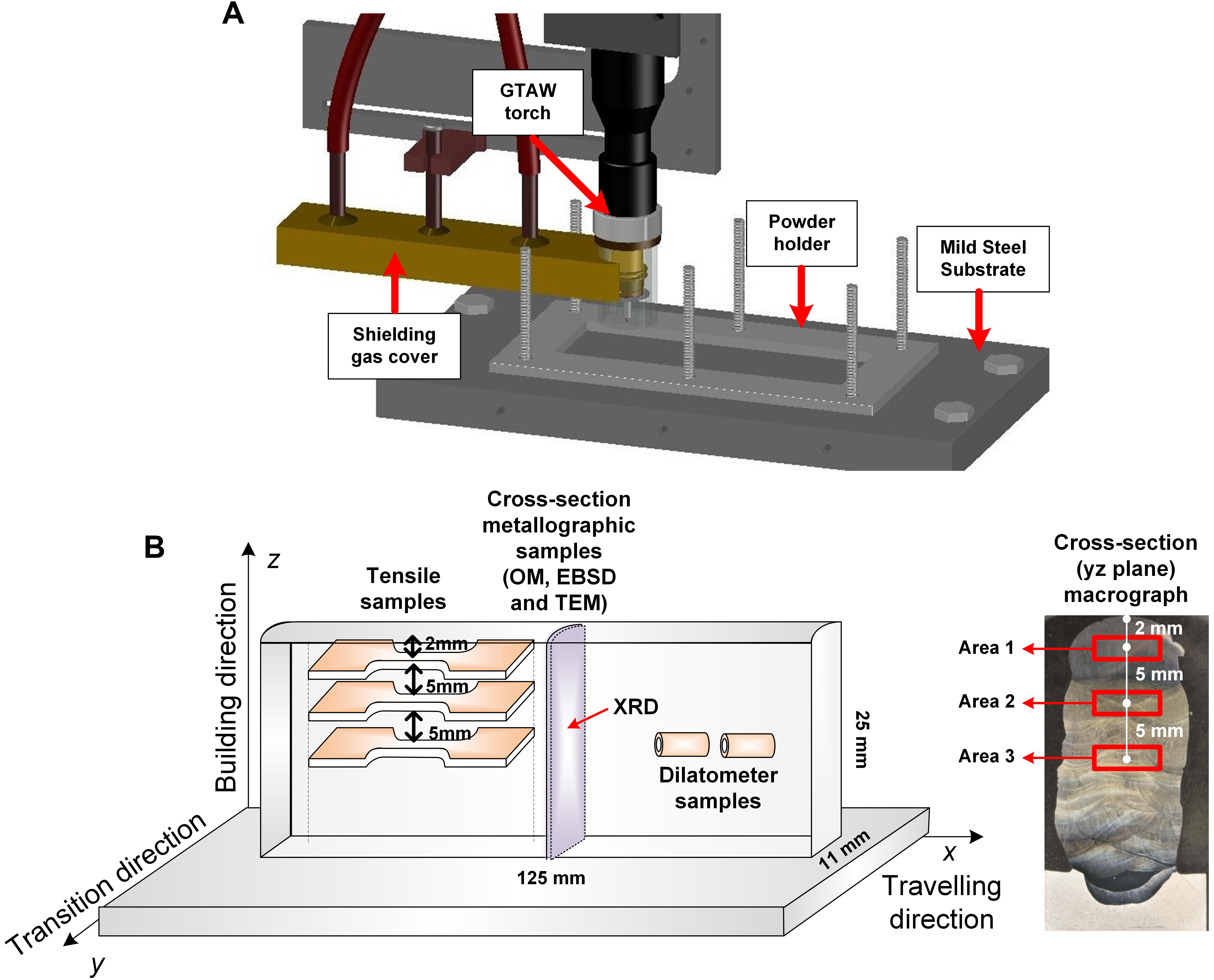
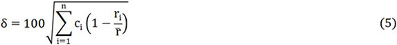
Figure 1. (A) Schematic of the powder-bed arc additive manufacturing (PAAM) system applied for producing high-entropy alloys (HEAs); (B) Schematic showing the dimensions of produced thin-wall HEA materials and the sampling locations for various characterization, together with a cross-sectional macrograph showing the areas for metallographic observations. Note that no macro-cracking or porosity was visible on the cross-section. OM: Optical microscope; EBSD: electron backscatter diffraction; TEM: transmission electron microscopy; XRD: X-ray diffraction.
Figure 1B schematically shows the extraction of samples from the as-fabricated FeCr0.4V0.3Ti0.2Ni1.3 thin-wall-structure material for various tests. Note that in the PAAM processing, the powder feedstocks and the deposited layers were constrained within the powder holder [Figure 1A]. It is believed that there should not be any significant horizontal offset of the individual layers that occurred during processing. The various widths of individual layers of the as-fabricated sample, as seen from Figure 1B are presumably caused by the variation of the melt flowability due to different thermal cycling conditions during processing. A cross-sectional sample for metallographic observations was extracted from the middle section of the as-fabricated materials and prepared by mounting, grinding, and polishing followed by electrical etching at room temperature in a solution consisting of 10 mL oxalic acid and 100 mL distilled water at 6 V DC for 20 s. To avoid the possible compositional modification in the initial deposition layers due to the diffusion of elements such as Fe and C from the steel substrate into the deposited HEA, we focused on the middle and top parts of the deposited material. It is worth mentioning that as recognized in previous work[32], not only the temperature gradient from subsequent deposition of additional layers but also the temperature cycling may cause the microstructural variations of additively manufactured materials and hence the heterogeneous materials mechanical properties along the building direction. Moreover, as this research involves a new material fabricated by a new process, it is considered necessary to understand if any differences exist in the microstructure and mechanical properties of various regions along the building direction (which experienced different thermal cycling). Three locations marked as Area 1, Area 2 and Area 3 in the cross-sectional sample [Figure 1B] were selected for microstructural analysis. Preliminary metallographic observation was performed using a Nikon Eclipse LV100NDA Optical Microscope (OM). X-ray diffraction (XRD) was also performed on the cross-sectional sample for the phase identification using a GBC MMA X-ray diffractometer with CuKα radiation (λ = 1.5406 Å). Further observations were performed using a JEOL® JSM-6490LA scanning electron microscope (SEM) equipped with an X-Max energy dispersive X-ray spectroscopy (EDS) detector. The EDS line scanning was conducted along the building direction from the top surface of the cross-sectional sample. Concurrent electron backscatter diffraction (EBSD) and EDS mappings were performed on the approximately middle region of the cross-sectional sample (Area 3) using a Zeiss® UltraPlusTM SEM equipped with EBSD and EDS detectors. Transmission electron microscopy (TEM) analyses were carried out using a JEM 2200FS TEM device operating at 200 kV, with the samples extracted from Area 3 and prepared by twin-jet polishing. In addition, the dilatometer measurements were performed by the Theta Industries Dilatoronic® Quence Dilatometor using hollow cylinder samples with dimensions of 10 mm length, 5 mm external diameter and 3.5 mm inner diameter. Two individual dilatometer tests were done in a temperature range from room temperature to 1250 °C at two different heating/cooling rates of 0.1 °C/s and 10 °C/s, respectively.
Three tensile samples were extracted from the HEA wall at the locations of 2 mm, 7 mm, and 12 mm away from the sample top surface, respectively, using electrical discharge machining. These sampling locations are consistent with those for metallographic observations (Areas 1, 2 and 3). The gauge volume of the tensile sample is 100 mm × 2 mm × 1.5 mm. An MTS370 load frame was used for the tensile tests at room temperature with a displacement rate of 0.6 mm/min. After the tensile tests, fractographic observation was performed using SEM. Moreover, Vickers microhardness measurement was performed by a Matsuzawa Via-F automatic Vickers hardness tester at a load of 500 N and a dwelling time of 10 s. The microhardness was measured along the central line of the cross-sectional sample at an interval of 0.5 mm.
RESULTS AND DISCUSSION
CALPHAD calculations
The CALPHAD modelling has been shown to be effective for predicting the phase formation and the solidification behavior in some HEA systems[33,34]. Figure 2 presents the equilibrium phase diagram and solidification simulation results on the phase transformation and compositional segregation using Thermo-Calc for the FeCr0.4V0.3Ti0.2Ni1.3 system. In agreement with the prediction from the empirical models, the Thermo-Calc calculated equilibrium phase diagram [Figure 2A] shows a dominant FCC phase in the designed alloy below 1300 °C. As expected, the Ni-Ti intermetallic in the form of Ni3Ti is also predicted to form in the alloy below ~1070 °C, due to the low mixing enthalpy of Ti and Ni elements and resultant low Gibbs free energy of this intermetallic formation in the system. Taking into account the fast solidification process that occurred during PAAM, which is applied for producing the designed HEA in the present work, the non-equilibrium Scheil solidification simulation based on the Scheil-Gulliver model[35] was performed. Figure 2B demonstrates the obtained liquid to solid phase transformation curve for the investigated HEA alloy, representing a fast solidification process away from the equilibrium. Furthermore, the elemental segregation during solidification of the HEA is calculated. As quantitatively shown in Figure 2C, with the progression of the solidification process in the studied HEA, the Ni and Ti elements appear to be enriched in the solid phase that forms in a later stage, whereas the other elements of Fe, Cr and V show depletion in the solid phase that solidifies subsequently. These simulations provide insights into the phase formation and the solidification process for the studied HEA system. In the following sections, the experimental characterization and analyses will be presented to further understand the microstructural characteristics and mechanical properties of the produced HEA using PAAM.
Figure 2. Thermo-Calc calculation results of the designed high-entropy alloy FeCr0.4V0.3Ti0.2Ni1.3: (A) equilibrium phase diagram; and Scheil solidification simulations showing the (B) phase transformation and (C) segregation of elements during solidification.
Microstructure and stability
Phase formation
Figure 3 shows the XRD pattern measured from the cross-sectional sample extracted from the produced HEA by PAAM. A dominant FCC phase is identified, as evidenced by three strong reflections of (111), (200) and (220) present in the observed 2θ range of 20°-80°. The lattice parameter of the FCC phase in the studied HEA is determined to be a = ~3.60 Å, lager than that of pure FCC Ni (a = ~3.52 Å), due to the solid-solution effect in the multi-component HEA. The Ni3Ti phase in the HEA system predicted by Thermo-Calc is not detected in the present XRD measurement, presumably due to the low volume fraction of this phase in the produced material, which is beyond the detection limit of the applied laboratory XRD.

Figure 3. A typical X-ray diffraction pattern of the as-fabricated high-entropy alloy.
Note that the present XRD analysis has limitations of only showing the dominant phase and its average structure in the HEA sample. To further understand the phase formation in the as-fabricated HEA material, TEM observations were performed on a typical sample extracted from Area 3 of the cross-sectional sample (as indicated in Figure 1). Figure 4 presents the obtained TEM results. Figure 4A shows a typical bright-field TEM image of the HEA sample together with a corresponding selected area electron diffraction (SAED) pattern under the [112] zone axis. The SAED data in Figure 4A confirms the dominant phase in the HEA sample to be an FCC structure, consistent with the XRD result. Interestingly, it is occasionally observed that an ordered phase of L12 structure is present in the microstructure, as shown in Figure 4B. This finding is obtained from the observation of weak superlattice reflections in the corresponding SAED pattern (see inset in Figure 4B) collected under [110] zone axis. This ordered L12 phase is not predicted in the equilibrium Thermo-Calc calculation [Figure 2A], suggesting that this phase is probably a metastable phase.
Figure 4. Transmission electron microscopy (TEM) observation of the produced high-entropy alloy (HEA) with the sample extracted from Area 3 (as indicated in Figure 1), showing the co-existence of matrix phases of the (A) disordered face-centred cubic (FCC) and (B) ordered L12 structures as well as the (C) needle-shaped Ni3Ti type precipitation and (D) spherical Ti-rich precipitation. The insets in (A) and (B) are corresponding selected area electron diffraction (SAED) patterns. The energy dispersive X-ray spectroscopy (EDS) results from the precipitates are included in (C) and (D). High-resolution TEM (HRTEM) data and the fast Fourier transform (FFT) pattern from the spherical precipitation are also shown in (D).
Figure 4C shows the needle-shaped precipitation observed in the microstructure. The corresponding EDS result shows that this precipitation is rich in Ni (~60 at.%) and Ti (~15 at.%), supporting the Thermo-Calc prediction [Figure 2B] for the formation of the minor Ni3Ti type precipitation in the studied HEA. The Ni3Ti type precipitation is also common in the maraging steels as a strengthening phase[36]. Moreover, as seen in Figure 4D, the spherical precipitation with a diameter of ~0.3 µm is present. The EDS analysis shows that this spherical precipitate is rich in Ti (~42 at.%). As shown in the inset in Figure 4D, the high-resolution TEM data and the corresponding Fast Fourier Transform pattern were present for this spherical Ti-rich precipitate, revealing its Hexagonal-Closed Packed structure. The Ti-rich precipitation is not predicted in the equilibrium phase diagram by Thermo-Calc [Figure 2A], suggesting its non-equilibrium nature. Considering the low solid solubility of Ti in the Fe- and Ni-based solid-solution system, it is believed that during the PAAM processing of the present FeCrVTiNi-based HEA material, the oversaturated Ti solutes in the melt may precipitate out as the Ti-rich precipitates in the produced HEA during solidification. The Ti-rich precipitate was also found in a BCC-structured VCrMnTi-based HEA in the as-cast condition[37]. Such precipitates may act as the getters for the O and H solutes in the alloys, potentially improving their resistance to oxidation and hydrogen embrittlement. However, the exact impact of the Ti-rich precipitation on the performance of the produced HEA remains to be understood.
Stability
To verify the stability of the phase(s) in the as-fabricated FeCr0.4V0.3Ti0.2Ni1.3 alloy, two individual dilatometer tests were performed at the heating and cooling rates of 0.1 °C/s and 10 °C/s, respectively. Figure 5 shows the recorded dilatometry curves. For both experiments, during the heating period, the strain of the dilatometer sample observed from its length changes almost linearly increases with increasing the temperature, suggesting that there is no evident phase transformation during the heating stage. Note that a smear-out slope discontinuity was clearly observed during cooling at 0.1 °C/s when the temperatures approach the range of ~850 °C to ~800 °C. This slope change is not conclusively identifiable for the case at the rate of 10 °C/s. According to the TEM investigation, the matrix of alloy consists of a disordered FCC phase and a small amount of ordered L12 structure. It is considered that the clear slope change in the dilatometer curve during cooling at a slow cooling of 0.1 °C/s was linked to the disorder to order phase transformation, similar to the observation of Ti2AlNb alloy[38]. It is also speculated that this phase transformation, as indicated by the slope change in the curve during cooling, would only readily occur at a relatively slow cooling for kinetics reasons. Because the additive manufacturing process used in this work involves a much higher cooling rate[39], the FCC matrix mainly remained in a disordered state in the as-fabricated FeCr0.4V0.3Ti0.2Ni1.3 HEA. Therefore, during the heating period of the dilatometer test, the strain of both samples shows a quasi-linear relationship with temperature. However, when the cooling rate is relatively low at 0.1 °C/s, the alloy seems to be more inclined to form an ordered L12 structure with the disorder to order transformation (which is likely kinetically limited) occurred during cooling at around
Figure 5. Dilatometry curves of the sample length changes (strain) as a function of temperature for the as-fabricated FeCr0.4V0.3Ti0.2Ni1.3 high-entropy alloy at different rates of (A) 0.1 °C/s and (B) 10 °C/s.
Dendritic microstructure and chemical segregation
Figure 6 shows the typical dendritic microstructure of the produced HEA by PAAM, observed by OM on the cross-section of Areas 1, 2 and 3 (as indicated in Figure 1). In general, cellular-like dendrites were formed in Area 1 as shown in Figure 6A, while the columnar grains were developed in Areas 2 and 3 along the building direction as shown in Figure 6B and C, respectively. The fusion line produced by arc welding between different deposited layers in the direction perpendicular to the x-z plane can be readily observed. Above the layer boundary, it exhibited relatively small columnar grains, which are regarded as the columnar prior grains[40] in Figure 6B. The length of the columnar grains in Areas 2 and 3 reaches up to ~1 mm, while the width of these grains is approximately 15 µm. The driving force of epitaxial columnar grains with dendrites along the deposition direction growth comes from the heat transfer from subsequent layers, which follows the highest thermal gradient[41]. The grains of preceding deposited layers are partially remelted by thermal cycling and format prior grains serving as the nucleus of the following grain growth. Therefore, the preferred grain growth direction is along the buildup direction, which is perpendicular to the direction of the solid-liquid interface[42,43]. In contrast, for the last deposition layers, the lack of following thermal cycling and accelerated cooling induced by the atmosphere transfers the dendrites into equiaxed morphologies[44].
Figure 6. Cross-sectional optical micrographs of the as-fabricated FeCr0.4V0.3Ti0.2Ni1.3 high-entropy alloy sample at selected areas indicated in Figure 1: (A) Area 1; (B) Area 2; and (C) Area 3.
To characterize the chemical segregation in the produced HEA as predicted by Thermo-Calc [Figure 2C], concurrent EBSD and EDS mappings across the dendritic microstructure on the cross-section (Area 3) of the as-fabricated HEA sample were performed, and the results are shown in Figure 7. The orientation map shows the development of small-angle grain boundaries (represented by fine lines) within the columnar grains. The corresponding EDS maps show that the elemental segregation across the dendrites occurred during solidification. Specifically, the Ni and Ti are positive segregation elements that are enriched in the interdendritic regions (solidified later compared with the dendritic cores), whereas the Fe and Cr are negative segregation elements that tend to segregate in the dendritic cores. Note that V is also a negative segregation element as predicted by Thermo-Calc [Figure 2C]. However, the segregation of V element in the microstructure was not clear from the experimental EDS map [Figure 7] due to its relatively low content in the produced FeCr0.4V0.3Ti0.2Ni1.3 HEA material and the limit of the EDS detection resolution. Overall, these experimental characterizations are in line with the Thermo-Calc prediction [Figure 2C], providing evidence and description of the micro-segregation process that is occurred during the solidification of the produced HEA by PAAM.
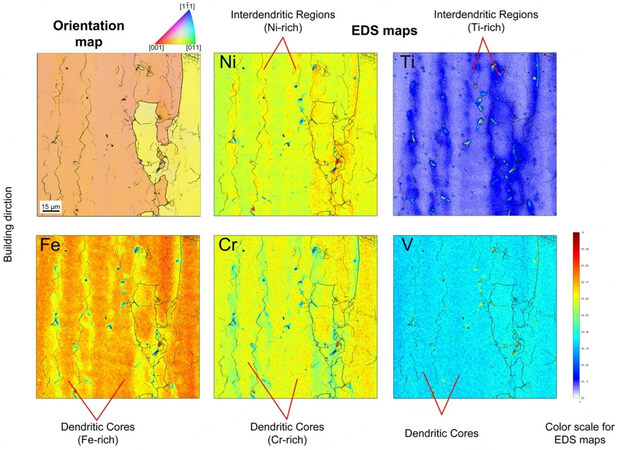
Figure 7. EBSD-based orientation map and corresponding energy dispersive X-ray spectroscopy (EDS) maps of Ni, Ti, Fe, Cr and V elements were collected from the cross-sectional sample in Area 3, as indicated in Figure 1. The thicker lines in the maps show the large-angle grain boundaries (misorientation angles > 7°), and fine lines represent small-angle grain boundaries (misorientation angles 0.15°-7°). The intensities of EDS maps are normalized to the same color scale. EBSD: Electron backscatter diffraction.
Heterogeneous mechanical properties and their microstructural origins
The mechanical properties of the as-fabricated FeCr0.4V0.3Ti0.2Ni1.3 HEA are accessed and correlated with their microstructural characteristics. To evaluate the homogeneity of the mechanical performance of the produced HEA material by PAAM, the microhardness was measured along the building direction on the cross-sectional sample, and the mechanical tensile tests were performed at room temperature on the samples extracted from different locations along the building direction. Figure 8 presents the obtained mechanical property results. As shown in Figure 8A, a significant variation of the microhardness ranging from 188 HV to 358 HV was observed along the building direction. The engineering stress-strain curves and tensile strengths and elongation results from the tensile tests on the samples extracted on similar heights of Areas 1, 2 and 3 (as indicated in Figure 1) are demonstrated in Figure 8B. Analogous to the microhardness results, distinctive tensile properties (strength and ductility) were observed at different sampling locations along the building direction. Specifically, the tensile test with the sample extracted at the height near the Area 1 shows the yield strength (YS), ultimate tensile strength (UTS) and elongation of ~468 MPa,
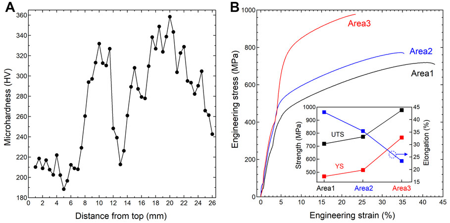
Figure 8. Mechanical properties of the as-fabricated FeCr0.4V0.3Ti0.2Ni1.3 alloy: (A) microhardness as a function of the distance from the sample top measured along the cross-section; (B) engineering stress-curves measured from similar heights of three areas (1, 2 and 3 as indicated in Figure 1), the inset shows the obtained ultimate tensile strength (UTS), yield strength (YS) and elongation.
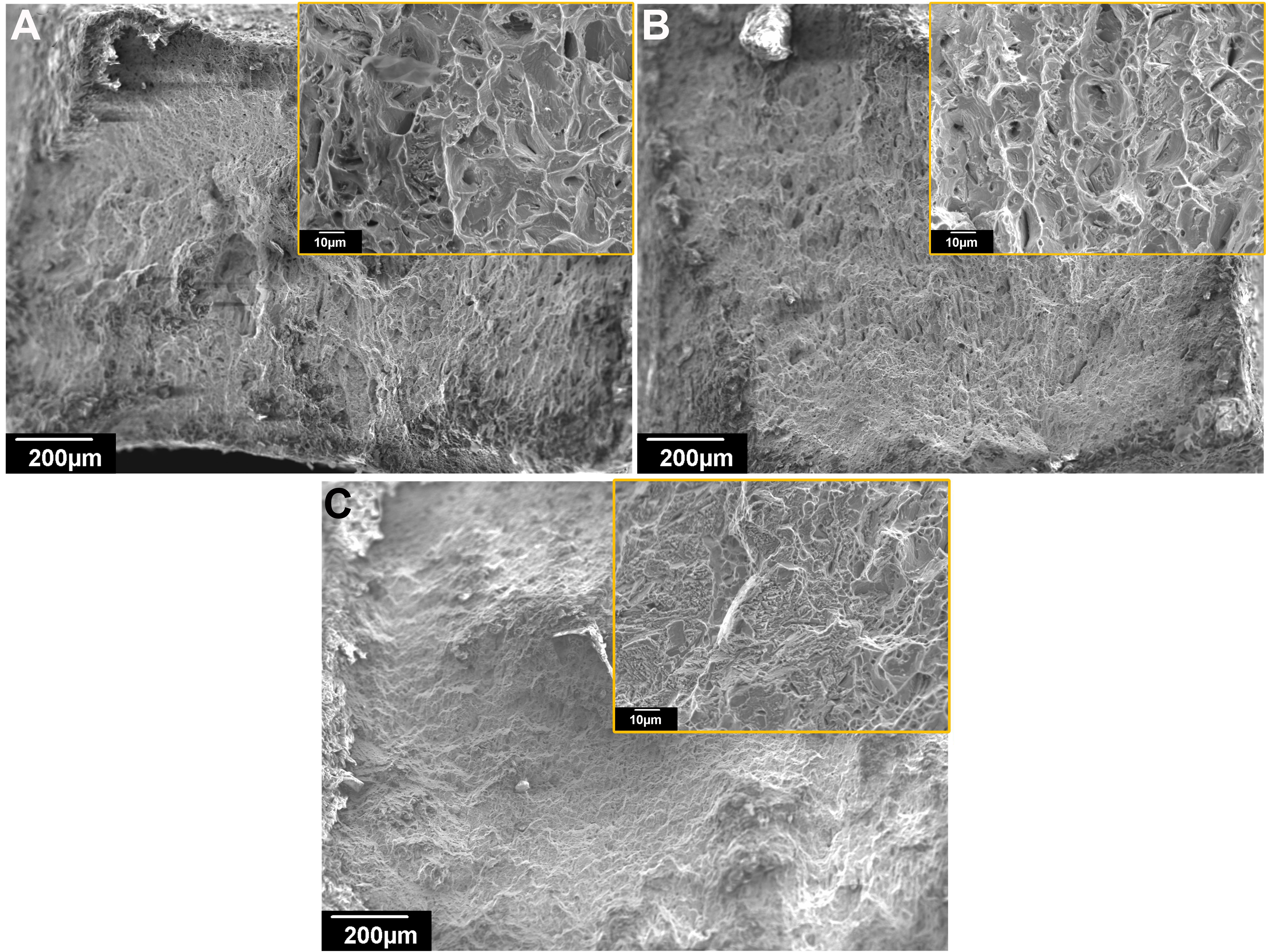
Figure 9. Scanning electron microscope (SEM) images showing the fracture morphologies after tensile testing of high-entropy alloy (HEA) samples extracted from various areas: (A) Area 1; (B) Area 2; and (C) Area 3.
Considering that a fundamental strengthening mechanism of HEAs is the solid-solution strengthening, we explored the correlation between the observed microhardness changes with the compositional variation in the designed alloy that is occurred due to segregation during solidification. The EDS line scanning on the cross-sectional sample was performed, and the obtained result is plotted together with the microhardness data and shown in Figure 10. Note that the quantification of these elements by EDS is in experimental error (within ± 1 at.%). However, the comparison of their relative contents measured from the same experiment is valid. It is interesting to observe that the distribution profiles of Cr and V elements resemble that of the microhardness data measured along the building direction, as highlighted by the yellow boxes in Figure 10. The elemental segregation as observed in Figure 7 is also confirmed by the EDS line scanning, as exemplified by the light blue box in Figure 10, which shows the enrichments of Ni and Fe elements are accompanied by the deficiencies of Cr and V elements. The Ti elemental segregation is not clearly identifiable in Figure 10. Based on these results, it is considered that the Cr and V elements play significant roles in the solid-solution strengthening in the designed alloy. However, other factors that may influence the strengthening, like residual stress and local texture changes, may not be ruled out, and further investigations are needed to advance the understanding.
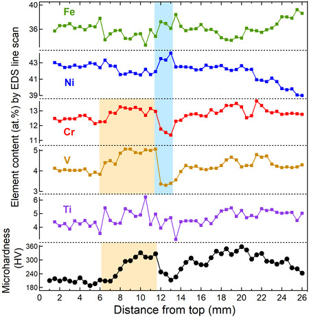
Figure 10. Energy dispersive X-ray spectroscopy (EDS) line scanning on the cross-section across the dendritic microstructure, showing the compositional variation as a function of the distance from the sample top. The errors of the EDS data for the measured elements (Fe, Cr, V, Ti and Ni) are estimated to be within ±1 at.% based on the counting statistics of X-ray spectra in the EDS measurements. To follow the correlation between the composition and microhardness, the microhardness data in Figure 7A is also included.
CONCLUSIONS
In this work, the currently known empirical thermodynamic models and the CALPHAD approach (Thermo-Calc) were used to design a low neutron cross-section, FCC HEA, with a nominal composition of FeCr0.4V0.3Ti0.2Ni1.3. The results predicted that a dominant FCC phase and minor Ni3Ti precipitation would form in the designed system. To verify the predictions, a new PAAM approach was used to fabricate the designed HEA material. A range of microstructural characterizations and mechanical tests were also performed. The principal conclusions in the following are obtained.
(1) The phase characterization acquired from XRD and TEM are generally coherent with the CALPHAD prediction. The FeCr0.4V0.3Ti0.2Ni1.3 HEA mainly consists of FCC single phase with a small quantity of Ni3Ti precipitations. However, a part of L12 ordered phase was detected by TEM investigation. The further dilatometer results suggested that the FeCr0.4V0.3Ti0.2Ni1.3 HEA prefers to generate L12 structure under equilibrium state, but the disordered phase was mainly produced in the as-fabricated alloy because of the high cooling rate of PAAM system.
(2) Microstructure evaluation of FeCr0.4V0.3Ti0.2Ni1.3 HEA buildup wall in three areas along the building direction were compared. In Area 1, cellular-like dendrites were formed, while columnar grains with elongated dendrites were exhibited in Areas 2 and 3. This phenomenon can be attributed to the thermal gradient along the building direction during the deposition process.
(3) The EBSD analysis support to the Thermo-Calc calculation about the partitioning of primary elements. The Ni and Ti are more inclined to solidified firstly and form the interdendritic region when the Fe, Cr and V gathered at the dendritic cores.
(4) The hardness of the as-fabricated HEA is heterogeneous from top to bottom, which would be caused by the variation of composition. The solid solution strengthening effect of Cr and V contributes to the increase of hardness obviously. Meanwhile, the tensile strength and 0.2% yield strength of FeCr0.4V0.3Ti0.2Ni1.3 wall increased from Area 1 to Area 3 (719 MPa to 976 MPa and 468 MPa to 766 MPa, respectively). The trade-off effect led to the decrease of ductility along with the height of the deposition wall, from 43% to 23%.
DECLARATIONS
Acknowledgments
The authors would like to acknowledge Mr. Tim Palmer (from ANSTO) for his technical support for the TEM sample preparation.
Authors’ contributions
Made substantial contributions to conception and design of the study and performed data analysis and interpretation: Dong B, Wang Z, Li H
Performed data acquisition, as well as provided administrative, technical, and material support: Zhu H, Muránsky O, Qiu Z, Shen C, Pan Z
Availability of data and materials
The raw/processed data required to reproduce these findings cannot be shared at this time as the data is used as part of an ongoing study.
Financial support and sponsorship
This work was supported by the 2018 Australian Nuclear Science and Technology Organisation (ANSTO) - University of Wollongong Joint Project Seed Funding. The author Dong B is supported by the China Scholarship Council (CSC).
Conflicts of interest
All authors declared that there are no conflicts of interest.
Ethical approval and consent to participate
Not applicable.
Consent for publication
Not applicable.
Copyright
© The Author(s) 2022.
Supplementary Materials
REFERENCES
1. Raj B, Vijayalakshmi M, Rao PV, Rao K. Challenges in materials research for sustainable nuclear energy. MRS Bull 2008;33:327-37.
3. Busby JT. Overview of structural materials in water-cooled fission reactors. Structural alloys for nuclear energy applications. Elsevier; 2019. p. 1-22.
4. Konings RJM, Stoller RE. Comprehensive nuclear materials. 2nd ed. Elsevier; 2020. p. 1-4653.
5. Volpe L, Burke M, Scenini F. Correlation between grain boundary migration and stress corrosion cracking of alloy 600 in hydrogenated steam. Acta Mater 2020;186:454-66.
6. Yeh J, Chen S, Lin S, et al. Nanostructured high-entropy alloys with multiple principal elements: novel alloy design concepts and outcomes. Adv Eng Mater 2004;6:299-303.
7. Zhang Y, Zuo TT, Tang Z, et al. Microstructures and properties of high-entropy alloys. Prog Mater Sci 2014;61:1-93.
8. He J, Wang H, Huang H, et al. A precipitation-hardened high-entropy alloy with outstanding tensile properties. Acta Mater 2016;102:187-96.
9. Shen Q, Kong X, Chen X. Fabrication of bulk Al-Co-Cr-Fe-Ni high-entropy alloy using combined cable wire arc additive manufacturing (CCW-AAM): microstructure and mechanical properties. J Mater Sci Mater Med 2021;74:136-42.
10. Zhang Y, Stocks GM, Jin K, et al. Influence of chemical disorder on energy dissipation and defect evolution in concentrated solid solution alloys. Nat Commun 2015;6:8736.
11. Zhang Y, Jin K, Xue H, et al. Influence of chemical disorder on energy dissipation and defect evolution in advanced alloys. J Mater Res 2016;31:2363-75.
12. Ullah MW, Xue H, Velisa G, et al. Effects of chemical alternation on damage accumulation in concentrated solid-solution alloys. Sci Rep 2017;7:4146.
13. Ayyagari A, Salloom R, Muskeri S, Mukherjee S. Low activation high entropy alloys for next generation nuclear applications. Materialia 2018;4:99-103.
14. King D, Cheung S, Humphry-baker S, et al. High temperature, low neutron cross-section high-entropy alloys in the Nb-Ti-V-Zr system. Acta Mater 2019;166:435-46.
15. Kareer A, Waite J, Li B, Couet A, Armstrong D, Wilkinson A. Short communication: ‘low activation, refractory, high entropy alloys for nuclear applications’. J Nucl Mater 2019;526:151744.
16. Xia SQ, Yang X, Yang TF, Liu S, Zhang Y. Irradiation resistance in Al x CoCrFeNi high entropy alloys. JOM 2015;67:2340-4.
17. Available from: https://periodictable.com/. [Last accessed on 5 Jan 2022].
18. Guo S, Liu C. Phase stability in high entropy alloys: formation of solid-solution phase or amorphous phase. Prog Nat Sci-Mater 2011;21:433-46.
19. King D, Middleburgh S, Mcgregor A, Cortie M. Predicting the formation and stability of single phase high-entropy alloys. Acta Mater 2016;104:172-9.
20. Dong B, Wang Z, Pan Z, et al. On the development of pseudo-eutectic AlCoCrFeNi2.1 high entropy alloy using Powder-bed Arc Additive Manufacturing (PAAM) process. Mater Sci Eng A Struct Mater 2021;802:140639.
21. Keller T, Lindwall G, Ghosh S, et al. Application of finite element, phase-field, and CALPHAD-based methods to additive manufacturing of Ni-based superalloys. Acta Mater 2017;139:244-53.
22. Agrawal P, Thapliyal S, Nene S, Mishra R, Mcwilliams B, Cho K. Excellent strength-ductility synergy in metastable high entropy alloy by laser powder bed additive manufacturing. Addit Manuf 2020;32:101098.
23. Zhang Y, Zhou Y, Lin J, Chen G, Liaw P. Solid-solution phase formation rules for multi-component alloys. Adv Eng Mater 2008;10:534-8.
24. Yang X, Zhang Y. Prediction of high-entropy stabilized solid-solution in multi-component alloys. Mater Chem Phys 2012;132:233-8.
25. Guo S, Hu Q, Ng C, Liu C. More than entropy in high-entropy alloys: forming solid solutions or amorphous phase. Intermetallics 2013;41:96-103.
26. Calvo-dahlborg M, Brown S. Hume-rothery for HEA classification and self-organizing map for phases and properties prediction. J Alloys Compd 2017;724:353-64.
27. Pradeep K, Tasan C, Yao M, Deng Y, Springer H, Raabe D. Non-equiatomic high entropy alloys: approach towards rapid alloy screening and property-oriented design. Mater Sci Eng A Struct Mater 2015;648:183-92.
28. Ma D, Yao M, Pradeep K, Tasan CC, Springer H, Raabe D. Phase stability of non-equiatomic CoCrFeMnNi high entropy alloys. Acta Mater 2015;98:288-96.
29. Takeuchi A, Inoue A. Classification of bulk metallic glasses by atomic size difference, heat of mixing and period of constituent elements and its application to characterization of the main alloying element. Mater Trans 2005;46:2817-29.
30. Kong D, Guo J, Liu R, et al. Effect of remelting and annealing on the wear resistance of AlCoCrFeNiTi0.5 high entropy alloys. Intermetallics 2019;114:106560.
31. Zhang J, Hu Y, Wei Q, et al. Microstructure and mechanical properties of RexNbMoTaW high-entropy alloys prepared by arc melting using metal powders. J Alloys Compd 2020;827:154301.
32. Wang H, Zhu Z, Chen H, et al. Effect of cyclic rapid thermal loadings on the microstructural evolution of a CrMnFeCoNi high-entropy alloy manufactured by selective laser melting. Acta Mater 2020;196:609-25.
33. Yao H, Qiao J, Hawk J, Zhou H, Chen M, Gao M. Mechanical properties of refractory high-entropy alloys: experiments and modeling. J Alloys Compd 2017;696:1139-50.
34. Gurao N, Biswas K. In the quest of single phase multi-component multiprincipal high entropy alloys. J Alloys Compd 2017;697:434-42.
35. Ohsasa K, Narita T, Shinmura T. Numerical modeling of the transient liquid phase bonding process of Ni using Ni-B-Cr ternary filler metal. JPE 1999;20:199-206.
36. Xu W, Rivera-díaz-del-castillo P, Wang W, et al. Genetic design and characterization of novel ultra-high-strength stainless steels strengthened by Ni3Ti intermetallic nanoprecipitates. Acta Mater 2010;58:3582-93.
37. Barron P, Carruthers A, Fellowes J, Jones N, Dawson H, Pickering E. Towards V-based high-entropy alloys for nuclear fusion applications. Scr Mater 2020;176:12-6.
38. Esin V, Mallick R, Dadé M, Denand B, Delfosse J, Sallot P. Combined synchrotron X-ray diffraction, dilatometry and electrical resistivity in situ study of phase transformations in a Ti2AlNb alloy. Mater Charact 2020;169:110654.
39. Wu B, Pan Z, Chen G, et al. Mitigation of thermal distortion in wire arc additively manufactured Ti6Al4V part using active interpass cooling. Sci Technol Weld Joi 2019;24:484-94.
40. Wang F, Williams S, Rush M. Morphology investigation on direct current pulsed gas tungsten arc welded additive layer manufactured Ti6Al4V alloy. Int J Adv Manuf Technol 2011;57:597-603.
41. Ma Y, Cuiuri D, Hoye N, Li H, Pan Z. Characterization of in-situ alloyed and additively manufactured titanium aluminides. Metall and Materi Trans B 2014;45:2299-303.
42. Qiu Z, Wu B, Zhu H, et al. Microstructure and mechanical properties of wire arc additively manufactured hastelloy C276 alloy. Mater Des 2020;195:109007.
43. Dong B, Pan Z, Shen C, Ma Y, Li H. Fabrication of copper-rich Cu-Al alloy using the wire-arc additive manufacturing process. Metall and Materi Trans B 2017;48:3143-51.
Cite This Article
Export citation file: BibTeX | RIS
OAE Style
Dong B, Wang Z, Zhu H, Muránsky O, Qiu Z, Shen C, Pan Z, Li H. Low neutron cross-section FeCrVTiNi based high-entropy alloys: design, additive manufacturing and characterization. Microstructures 2022;2:2022003. http://dx.doi.org/10.20517/microstructures.2021.09
AMA Style
Dong B, Wang Z, Zhu H, Muránsky O, Qiu Z, Shen C, Pan Z, Li H. Low neutron cross-section FeCrVTiNi based high-entropy alloys: design, additive manufacturing and characterization. Microstructures. 2022; 2(1): 2022003. http://dx.doi.org/10.20517/microstructures.2021.09
Chicago/Turabian Style
Dong, Bosheng, Zhiyang Wang, Hanliang Zhu, Ondrej Muránsky, Zhijun Qiu, Chen Shen, Zengxi Pan, Huijun Li. 2022. "Low neutron cross-section FeCrVTiNi based high-entropy alloys: design, additive manufacturing and characterization" Microstructures. 2, no.1: 2022003. http://dx.doi.org/10.20517/microstructures.2021.09
ACS Style
Dong, B.; Wang Z.; Zhu H.; Muránsky O.; Qiu Z.; Shen C.; Pan Z.; Li H. Low neutron cross-section FeCrVTiNi based high-entropy alloys: design, additive manufacturing and characterization. Microstructures. 2022, 2, 2022003. http://dx.doi.org/10.20517/microstructures.2021.09
About This Article
Copyright

Data & Comments
Data
0

 Cite This Article 20 clicks

 Like This Article 0
likes
Like This Article 0
likes


Comments
Comments must be written in English. Spam, offensive content, impersonation, and private information will not be permitted. If any comment is reported and identified as inappropriate content by OAE staff, the comment will be removed without notice. If you have any queries or need any help, please contact us at support@oaepublish.com.